
Graphical method for generating heat dissipation topology by zero-depletion grid curved surface

A mesh and surface technology, which is applied in the field of heat dissipation performance optimization design of cold plates, can solve the problems of lack of geometric boundaries in design results, difficulties in machining and manufacturing of mechanical structures, and topology optimization methods that cannot meet heat dissipation topology optimization design.

Active Publication Date: 2020-10-27
XI AN JIAOTONG UNIV
View PDF3 Cites 9 Cited by
  • Summary
  • Abstract
  • Description
  • Claims
  • Application Information

AI Technical Summary

Problems solved by technology

[0003] High power and high heat flux are major problems that continue to exist in the development of modern electronics. Many electronic devices, such as electronic chips, batteries, and CPUs, are affected by heat loads. Most of the heat is harmful and must be Take the heat away from the working area in time to ensure the normal operation and service life of electronic equipment and tools; the problem of heat dissipation in electronic equipment has been well developed in the past few decades, and mainstream cold plate design methods include fluidic microchannel heat sinks , special-shaped channel design and multi-layer cold plate heat exchanger, etc.; however, the traditional cold plate design method relies on the experience of engineers, and it is difficult to efficiently and targetedly complete the cooling target of complex equipment
[0004] Different from the traditional design method, the topology optimization design method is based on calculation, reasonably distributes materials in the design domain, so as to achieve the optimal distribution and obtain the best heat dissipation effect, and the pixel-based variable density method (SIMP), evolution Algorithm (ESO), RAMP, level set method (LST) based on high-dimensional space description; in SIMP equivalent variable density method, the design domain is discretized into pixels of the same size, and the structure is represented by black and white pixels and their interpolation. Freely change the number of genus in the design domain, the concept is simple, the threshold of use is low, and it has been widely used in many fields. However, the pixel points of the variable density method are extremely difficult to converge, and there are serious "grayscale" and "checkerboard" phenomena , so that the design result lacks a clear geometric boundary, and cannot accurately describe the geometric shape of the mechanical structure; in addition, the design result of the variable density method lacks clear design parameters, and it is difficult to control the structural feature size, which has caused serious damage to the processing and manufacturing of the mechanical structure. Great difficulty; the level set method uses high-dimensional space description to realize the variable topology function of the underlying structure through the movement and deformation of the upper grid. Using the projection method, the geometric boundary of the structure can be clearly and accurately described. However, the initial layout of the level set method The dependence is strong, and the ability to change topology mainly depends on the movement of the upper grid and the number of components, and it is difficult to realize the free change of genus in the design domain; therefore, the current topology optimization method cannot meet the requirements of thermal topology optimization design in many cases

Method used


Image

  • Graphical method for generating heat dissipation topology by zero-depletion grid curved surface
  • Graphical method for generating heat dissipation topology by zero-depletion grid curved surface
  • Graphical method for generating heat dissipation topology by zero-depletion grid curved surface

Examples


Embodiment Construction

[0098] The present invention will be further described below in conjunction with drawings and embodiments.

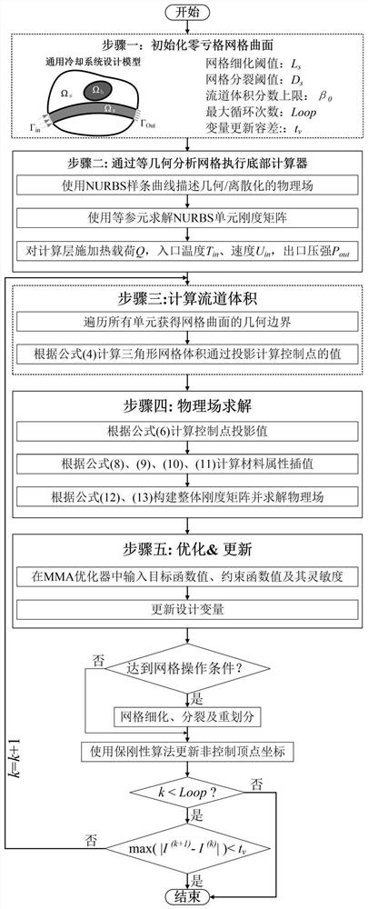
[0099] Such as figure 1 As shown in , a graphical method for generating cooling topology from zero-genus mesh surfaces includes the following steps:

[0100] 1) Define design conditions:

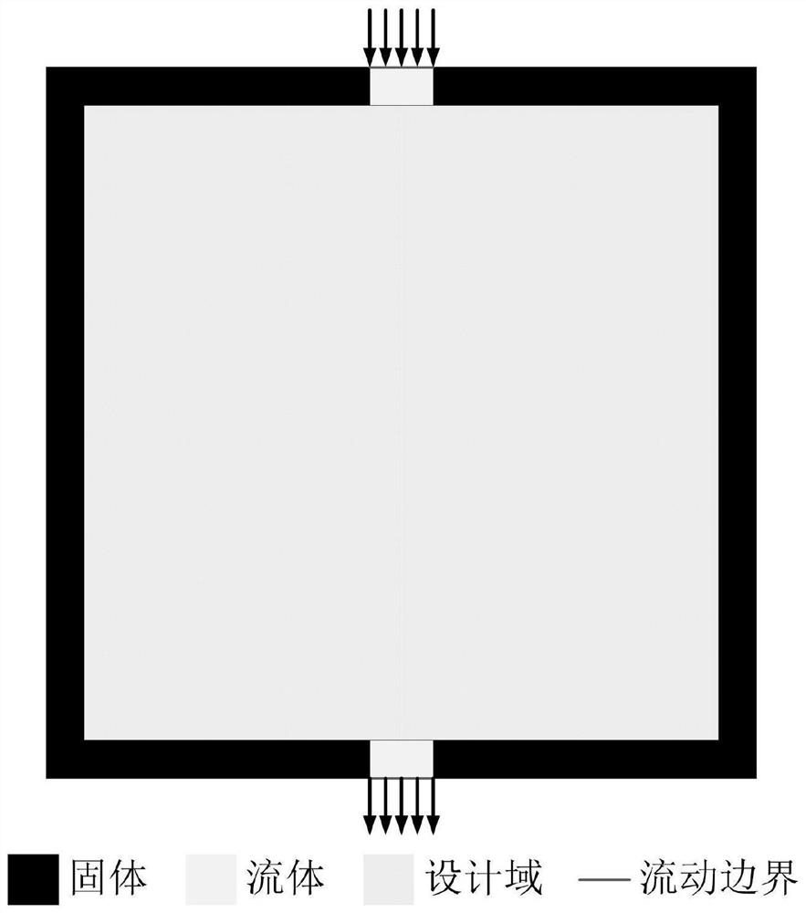
[0101] Taking the two-dimensional square planar structure as the design domain, the size parameter of the design domain is 0.01m×0.01m, the internal uniform heat load is Q, the boundaries of the design domain are all adiabatic boundaries, and the fluid inlet and outlet are respectively located in the center of the upper and lower boundaries of the design domain. The width is 0.001m, such as figure 2 shown;

[0102] 2) Construct an initial zero-genus mesh surface:

[0103] Take n non-overlapping points as the vertices of the geometric model in the zero-genus grid to construct a square grid, and the coordinate values ​​of each vertex are (x i ,y i ), i=1,2,…,n, the parametric geo...


PUM


Abstract

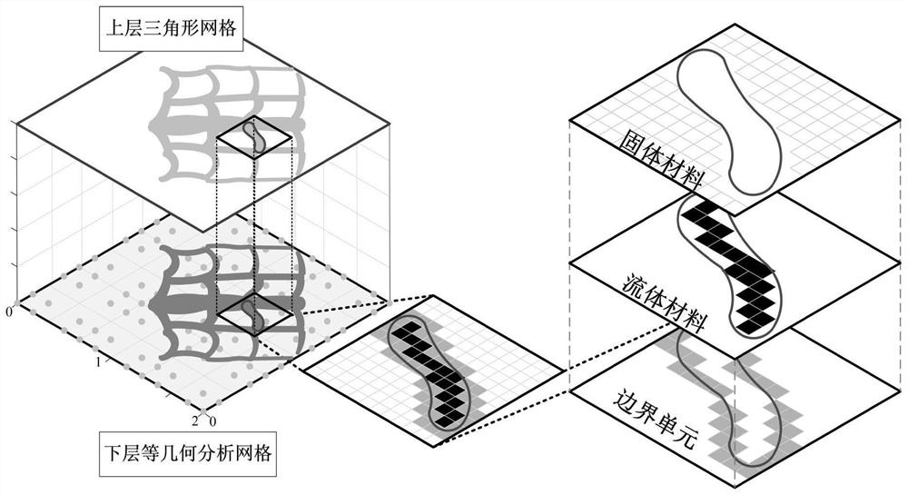
The invention discloses a graphical method for generating a heat dissipation topology by a zero-depletion grid curved surface. The method comprises the following steps: a heat dissipation structure isdesigned by utilizing a double-layer grid; the upper layer uses a zero-depletion deformable triangular mesh to describe a topological geometric model, and a heat dissipation topological structure canbe generated only through one component, so that the initial layout dependence is eliminated, a clear geometric boundary is obtained, design variables are reduced, and the calculation speed is increased; the lower layer uses an isogeometric unit to perform heat flow coupling steady-state heat conduction calculation and sensitivity analysis; the geometric model is accurately described by the analysis model, errors caused by the fact that a traditional finite element adopts a piecewise function to approach the geometric model are avoided, the solving precision of the fluid heat dissipation problem is improved, redundant grid division links in a classical finite element are avoided in the isogeometric analysis process, and the calculation cost is saved; a more reliable thought is provided for topological optimization of the heat dissipation structure.

Description

technical field [0001] The invention relates to the technical field of heat dissipation performance optimization design of a cold plate, in particular to a graphics method for generating heat dissipation topology from a zero-genus grid surface. [0002] technical background [0003] High power and high heat flux are major problems that continue to exist in the development of modern electronics. Many electronic devices, such as electronic chips, batteries, and CPUs, are affected by heat loads. Most of the heat is harmful and must be Take the heat away from the working area in time to ensure the normal operation and service life of electronic equipment and tools; the problem of heat dissipation in electronic equipment has been well developed in the past few decades, and mainstream cold plate design methods include fluidic microchannel heat sinks , special-shaped channel design and multi-layer cold plate heat exchanger, etc.; however, the traditional cold plate design method rel...

Claims


Application Information

Patent Timeline
IPC IPC(8): G06F30/23G06F111/04G06F119/08
CPCG06F30/23G06F2119/08G06F2111/04
Inventor 李宝童张路宽刘宏磊唐文豪洪军
Owner XI AN JIAOTONG UNIV
Learn More