Eureka AIR delivers breakthrough ideas for toughest innovation challenges, trusted by R&D personnel around the world.

Intelligent uncinate joint stress monitoring system and method

A stress monitoring and uncinate technology, applied in the field of medical devices, can solve the problems of inability to flexibly monitor neck activities in real time, low success rate, and infection.

Pending Publication Date: 2020-10-30
WEST CHINA HOSPITAL SICHUAN UNIV
View PDF0 Cites 3 Cited by
  • Summary
  • Abstract
  • Description
  • Claims
  • Application Information

AI Technical Summary

Problems solved by technology

However, this method often has a low success rate and is relatively clumsy. It is often only suitable for a single study of cadaver biomechanics. In the human body or animal experiments, the wire passes through the skin to reach the outside of the body, and there is a risk of infection and fracture. Inserting it at the same time The stress sheet between the fusion device and the bone surface is also not conducive to bone healing; at the same time, after the external device for stress monitoring is connected, it is inconvenient for human or experimental animals to move
[0007] Existing technologies cannot flexibly monitor neck movements in real time, identify neck movement postures based on neck movement data, and calculate stress levels corresponding to different neck movement postures; cannot carry out early warning and correction of unhealthy neck movement postures ; It is impossible to collect, record and analyze the data of the neck movement posture and its corresponding stress, and further provide effective big data support for the design and optimization of the hook-vertebral joint fusion device

Method used


Image

  • Intelligent uncinate joint stress monitoring system and method
  • Intelligent uncinate joint stress monitoring system and method
  • Intelligent uncinate joint stress monitoring system and method

Examples


Embodiment Construction

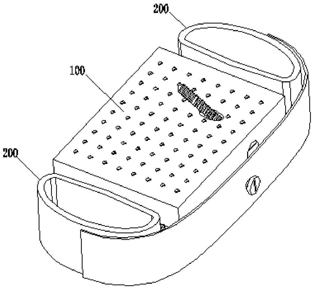
[0030] attached figure 1 It is a schematic diagram of the structure of the hook-vertebral joint fusion device applied in the present invention, including an intervertebral body support body 100 and a hook-vertebral joint fusion component 200, and a hook-vertebral joint fusion component is respectively arranged on the left and right sides of the intervertebral body support body 100 200, the upper surface and the lower surface of the interbody support body 100 and the hook vertebra joint fusion component 200 are provided with a layer of cage material, and there is a layer of cavity under the cage material.

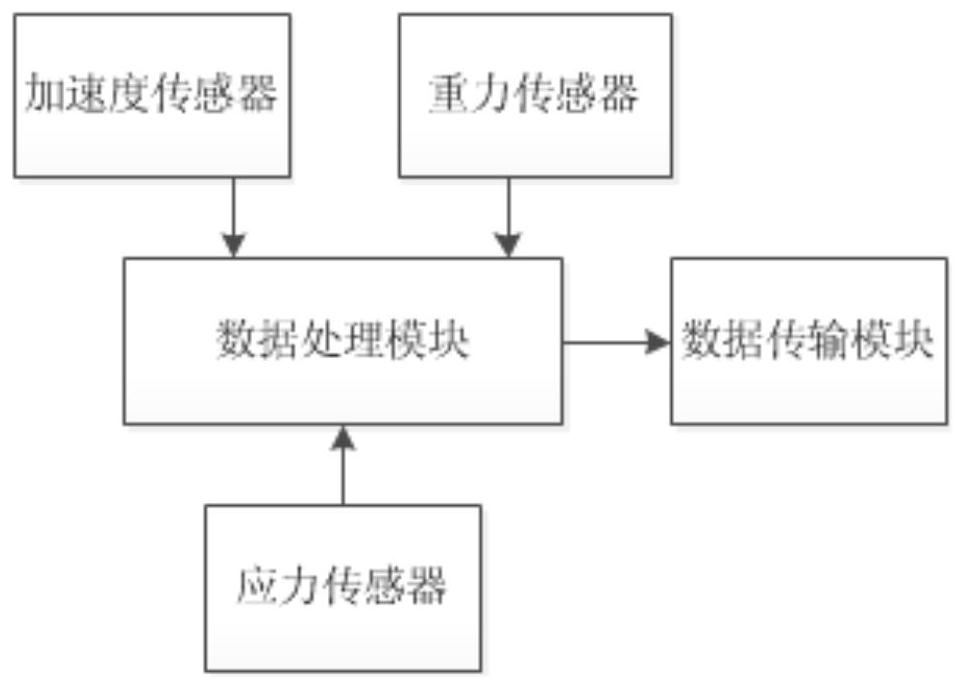
[0031] attached figure 2It is a schematic block diagram of the circuit structure of the intelligent hook-vertebral joint stress monitoring system of the present invention, including a stress sensor, an acceleration sensor, a gravity sensor, a data transmission module and a data processing module, and the stress sensor, the acceleration sensor and the gravity sensor are all ...


PUM


Abstract

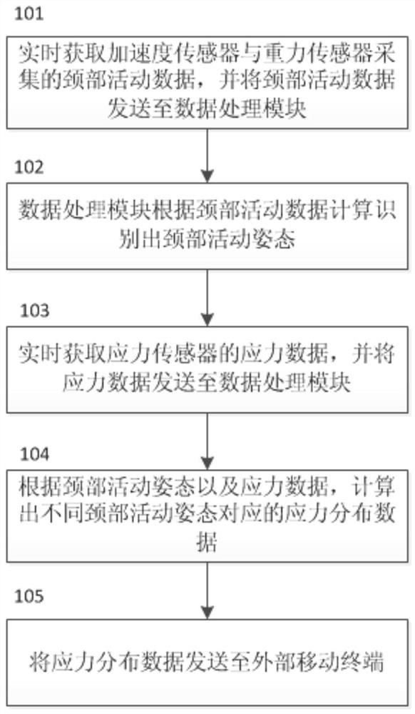
The invention relates to the field of medical instruments, in particular to an intelligent uncinate joint stress monitoring system and a method. The neck movement can be monitored flexibly in real time, the movement posture of the neck can be recognized according to the neck movement data, the stress distribution data corresponding to different neck movement postures can be obtained in combinationwith the stress data, and effective big data support is further provided for designing and optimizing the interbody fusion cage. According to the scheme, neck activity data collected by an acceleration sensor and a gravity sensor are obtained in real time, and the neck activity data are sent to a data processing module; the data processing module is used for calculating and identifying a neck movement posture according to the neck movement data; stress data of the stress sensor is acquired in real time, and sending of the stress data to the data processing module is realized; calculating of stress distribution data is carried out corresponding to different neck movement postures according to the neck movement postures and the stress data; and the stress distribution data is sent to an external mobile terminal through the data transmission module. The system is suitable for uncaria joint stress monitoring research.

Description

technical field [0001] The invention relates to the field of medical devices, in particular to an intelligent hook vertebra joint stress monitoring system and method. Background technique [0002] Anterior cervical decompression and fusion (ACDF) has always been an effective and classic surgical method for the treatment of cervical degenerative diseases. Anterior cervical plate, intervertebral fusion cage and other implant materials can improve the initial stability, support strength and bone graft fusion rate of ACDF surgery. The basic purpose of the design of the intervertebral fusion cage is to maintain and improve the curvature of the cervical spine on the basis of providing good initial stability and support strength, and to provide a good biological and biomechanical environment for intervertebral fusion to promote bone graft fusion. [0003] The stress analysis of hook vertebra joint fusion is of great help to explore the mechanism of hook vertebra joint fusion and i...

Claims


Application Information

Patent Timeline
Patent Type & Authority Applications(China)
IPC IPC(8): A61F2/44A61B5/22A61B5/11
CPCA61F2/4465A61B5/11A61B5/1116A61B5/22A61B5/686A61B5/6878A61B5/746A61B2562/0219A61B2562/02
Inventor 杨毅刘浩
Owner WEST CHINA HOSPITAL SICHUAN UNIV
Why Eureka
Eureka Blog
Learn More