High-temperature corrosion-resistant push plate of garbage incinerator and preparation method thereof
A waste incinerator and pusher plate technology, applied in the field of surface engineering, can solve problems such as short service life and affecting the long-term stable service of the incinerator
- Summary
- Abstract
- Description
- Claims
- Application Information
AI Technical Summary
Problems solved by technology
Method used
Image

Examples
preparation example Construction
[0045] The second aspect of the present invention relates to a method for preparing the high-temperature abrasion-resistant pusher plate of a garbage incinerator as described in the first aspect of the present invention, which includes:
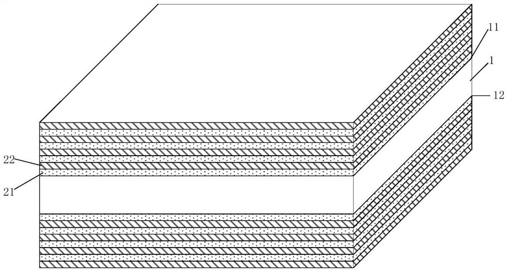
[0046] Step B, in the closed liquid forging die (conventional) on the hydraulic press, alternately lay Al-Fe on the upper surface 11 and the lower surface 12 of the pusher plate 1 from inside to outside 3 o 4 Mixed powder 21 and Ti-C mixed powder 22, the layer next to the pusher plate and the lower surface is Al-Fe 3 o 4 Mixed powder 21, the outermost layer is Ti-C mixed powder 22, see figure 2 ;
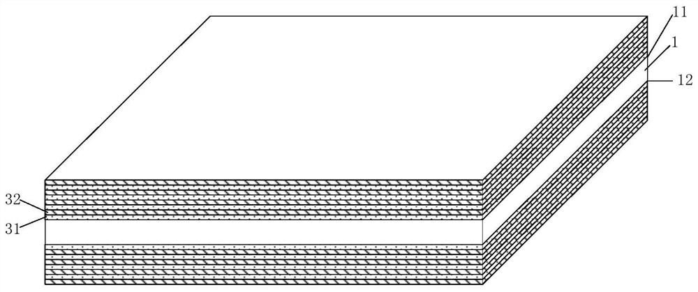
[0047] Step C, alternately laying Al-Fe 3 o 4 The mixed powder 21 and the Ti-C mixed powder 22 are pressed together to form Al-Fe alloys laid alternately from the inside to the outside on the upper surface 11 and the lower surface 12 of the pusher plate 1. 3 o 4 Powder blank 31 and Ti-C powder blank 32, the layer next to the pusher plate an...
Embodiment 1
[0077] (1) Prepare Ti+C=TiC self-propagating powder material and 8Al+3Fe respectively according to the principle of self-propagating reaction 3 o 4 = 4 Al 2 o 3 +9Fe self-spreading powder material (powder particle size is 200-300 mesh), mix the respective spreading powder materials evenly to obtain Al-Fe 3 o 4 Mixed powder and Ti-C mixed powder;
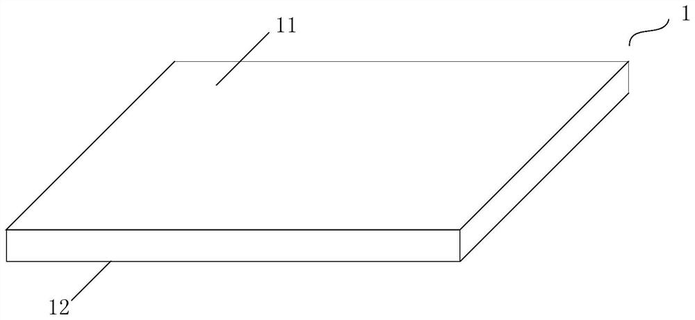
[0078] (2) The upper surface 11 and the lower surface 12 of the pushing plate 1 in the closed liquid forging die on the hydraulic press (see figure 1 ) into Al-Fe in turn 3 o 4 The mixed powder 21 and the Ti-C mixed powder 22 are laid repeatedly and alternately in 8 layers. The order of the mixed powder layers laid alternately on the upper surface 11 and the lower surface 12 of the pushing plate 1 from the inside to the outside is: Al-Fe 3 o 4 Mixed powder 21 / Ti-C mixed powder 22 / Al-Fe 3 o 4 Mixed powder 21 / Ti-C mixed powder 22 / Al-Fe 3 o 4 Mixed powder 21 / Ti-C mixed powder 22 / Al-Fe 3 o 4Mixed powder 21 / Ti-C mixed powder...
Embodiment 2
[0085] The difference between step (2) of this embodiment and embodiment 1 is that 6 layers are alternately laid repeatedly, and the order of the mixed powder layers laid alternately from the inside to the outside on the upper surface 11 and lower surface 12 of the pushing plate 1 is: Al-Fe 3 o 4 Mixed powder 21 / Ti-C mixed powder 22 / Al-Fe 3 o 4 Mixed powder 21 / Ti-C mixed powder 22 / Al-Fe 3 o 4 Mixed powder 21 / Ti-C mixed powder 22;
[0086] The difference between step (3) of this embodiment and embodiment 1 is that the order of the mixed powder layers laid alternately from the inside to the outside on the upper surface 11 and the lower surface 12 of the pusher plate 1 is: Al-Fe 3 o 4 Powder blank 31 / Ti-C powder blank 32 / Al-Fe 3 o 4 Powder blank 31 / Ti-C powder blank 32 / Al-Fe 3 o 4 Powder blank 31 / Ti-C powder blank 32;
[0087] The difference between step (4) of this embodiment and embodiment 1 is that the TiC / Fe-Al that constitutes the high-temperature abrasion-resistan...
PUM
| Property | Measurement | Unit |
|---|---|---|
| thickness | aaaaa | aaaaa |
| thickness | aaaaa | aaaaa |
Abstract
Description
Claims
Application Information
 - R&D
- Intellectual Property
- Life Sciences
- Materials
- Tech Scout
- Unparalleled Data Quality
- Higher Quality Content
- 60% Fewer Hallucinations
Browse by: Latest US Patents, China's latest patents, Technical Efficacy Thesaurus, Application Domain, Technology Topic, Popular Technical Reports.
© 2025 PatSnap. All rights reserved.Legal|Privacy policy|Modern Slavery Act Transparency Statement|Sitemap|About US| Contact US: help@patsnap.com