Laser lighting equipment

A technology of laser lighting and equipment, applied in the field of optics, can solve problems such as unsatisfactory overall effect, high beam coherence, speckle, etc., to achieve the effect of improving light energy utilization, improving spot quality, and reducing coherence

Inactive Publication Date: 2020-11-03
CHANGCHUN INST OF OPTICS FINE MECHANICS & PHYSICS CHINESE ACAD OF SCI
View PDF14 Cites 2 Cited by
  • Summary
  • Abstract
  • Description
  • Claims
  • Application Information

AI Technical Summary

Problems solved by technology

However, due to the random scattering of the ground glass, the coherence of each sub-beam output by the aspheric lens and the microlens array is high, and the speckle phenomenon is serious, and the diffractive optical element can only achieve the required spot shape and uniformity within a certain distance range. The overall effect is not ideal

Method used


Image

  • Laser lighting equipment

Examples


Embodiment Construction

[0023] The following will clearly and completely describe the technical solutions in the embodiments of the present invention with reference to the accompanying drawings in the embodiments of the present invention. Obviously, the described embodiments are only some, not all, embodiments of the present invention. Based on the embodiments of the present invention, all other embodiments obtained by persons of ordinary skill in the art without making creative efforts belong to the protection scope of the present invention.

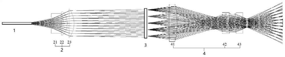
[0024] The invention provides a laser lighting device, such as figure 1 shown, including:

[0025] A laser is used to emit a laser beam, which is coupled into the optical fiber 1;

[0026] Optical fiber 1, used to transmit the laser beam;

[0027] A collimating optical system 2 is used to collimate the laser beam emitted from the optical fiber 1 and illuminate the surface of the random microlens array 3;

[0028] The random microlens array 3 is used to homo...


PUM

PropertyMeasurementUnit
wavelengthaaaaaaaaaa
diameteraaaaaaaaaa

Abstract

The invention discloses laser lighting equipment, comprising: a laser for emitting a laser beam which enters an optical fiber through coupling; the optical fiber which is used for transmitting laser beams; the collimating optical system which is used for collimating the laser beams emitted by the optical fiber and illuminating the laser beams to the surface of the random micro lens array; the random micro-lens array which is used for homogenizing and shaping the laser beams, emitting light beams with fixed divergence angles and enabling the light beams to enter the angle adjusting optical system; and the angle adjusting optical system which is used for adjusting the emergent light beam of the random micro lens array to a required divergence angle and then emitting the emergent light beam.According to the invention, the random micro-lens array is adopted to homogenize and shape the laser beam, so that the emergent beam can be in a fixed divergence angle range, the light energy utilization rate is improved, the coherence of the beam is reduced to a certain extent, the speckle effect is reduced, and the quality of the shaped light spot is further improved; meanwhile, the angle adjusting optical system is used for adjusting the emergent light beams of the random micro-lens array, and the final emergent light beam angle is controlled.

Description

technical field [0001] The invention relates to the field of optical technology, in particular to a laser lighting device. Background technique [0002] Laser has the characteristics of high brightness, narrow spectral width, and good directionality. It has its unique advantages when used in lighting. Laser lighting technology is widely used in national defense engineering, aerospace engineering, night vision monitoring, laser display and other fields. However, due to the good monochromaticity of laser and strong coherence, laser speckle will be generated when it illuminates the surface of an object. At the same time, due to the large difference in the divergence angles of the laser fast and slow axes output by the commonly used semiconductor lasers, it is not possible to output a uniform circular spot. Generally, the light spot output by coupling into the optical fiber for output presents a Gaussian distribution, which cannot show good uniformity on the required illuminati...

Claims


Application Information

Patent Timeline
Patent Type & Authority Applications(China)
IPC IPC(8): G02B27/09G02B27/48
CPCG02B27/0916G02B27/0927G02B27/0961G02B27/48
Inventor 付瀚毅刘伟奇康玉思寇伟
Owner CHANGCHUN INST OF OPTICS FINE MECHANICS & PHYSICS CHINESE ACAD OF SCI
Why Eureka
Try Eureka