
Ultrasound system for shear wave imaging in three dimensions

An ultrasonic imaging system and shear wave technology, applied in the field of medical ultrasonic imaging systems, can solve the problems of slow shear wave and attenuation

Pending Publication Date: 2020-11-03
KONINKLJIJKE PHILIPS NV
View PDF9 Cites 1 Cited by
  • Summary
  • Abstract
  • Description
  • Claims
  • Application Information

AI Technical Summary

Problems solved by technology

Laterally propagating shear waves travel slowly, usually meters per second or less, making shear waves easy to detect, but decay rapidly over distances of a few centimeters or less

Method used


Image

  • Ultrasound system for shear wave imaging in three dimensions
  • Ultrasound system for shear wave imaging in three dimensions
  • Ultrasound system for shear wave imaging in three dimensions

Examples


Embodiment Construction

[0019] specific implementation plan

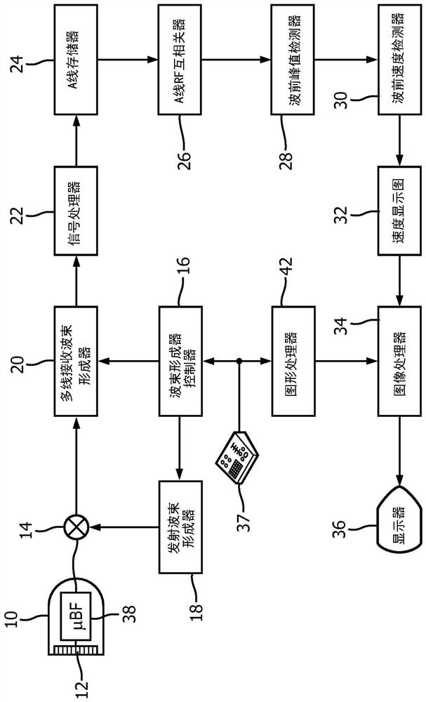
[0020] first reference figure 1 , shows in block diagram form an ultrasonic system for measuring hardness using shear waves constructed in accordance with the principles of the present invention. The ultrasound probe 10 has a two-dimensional matrix array 12 of transducer elements for transmitting and receiving ultrasound signals. Two-dimensional array transducers can scan a two-dimensional (2D) plane by transmitting a beam on a single plane in the body and receiving return echo signals, and can also be used to scan through different regions of the body's volume (3D). A volumetric area is scanned by transmitting and receiving beams in a direction and / or in a plane. The array elements are coupled to a microbeamformer 38 located in the probe, which controls transmission through the elements and processes echo signals received from groups or sub-arrays of elements into partial beamformers. signal of. Via a transmit / receive (T / R) switch 14,...


PUM


Abstract

An ultrasound imaging system for analyzing tissue stiffness by shear wave measurement comprises a matrix array probe which acquires shear wave velocity data from three planes of a volumetric region ofinterest. The velocity data is used to color-code pixels in the planes in accordance with their estimated tissue stiffness. The planes are displayed in their relative spatial orientation in an isometric or perspective display. The positions and orientations of the planes can be changed from the system user interface, enabling a clinician to view selected planes of stiffness information which intersect the region of interest.

Description

technical field [0001] The present invention relates to medical ultrasound imaging systems, and in particular to ultrasound systems that use shear waves to perform measurements of tissue stiffness or elasticity. Background technique [0002] An advantage of ultrasound imaging and other imaging modalities is the ability to anatomically visualize the features and functions of the pathology or tissue being imaged, in addition to delineating the structure of the pathology and tissue in the body. This is done by acquiring two images of the anatomy, one structural and the other parametric. These two images are then superimposed for display in anatomical registration. The basic parametric image in ultrasound is the color flow image, in which a B-mode image of tissue structures is overlaid with a color image representing the direction and velocity of blood flow in blood vessels and other structures of the tissue. The structure of the blood vessel wall constructs the blood flow inf...

Claims


Application Information

Patent Timeline
IPC IPC(8): A61B8/08A61B8/00
CPCA61B8/463A61B8/466A61B8/467A61B8/483A61B8/485A61B8/523A61B8/54G01N29/0654G01N29/262G01N2291/02827G01N2291/02475G01S7/52042G01S15/8993G01S7/52071G01S15/8915A61B8/14A61B8/4488A61B8/469
Inventor 黃圣文谢华M·阮C·阿马多尔卡拉斯卡尔J-L·F-M·罗伯特V·T·沙姆达莎尼
Owner KONINKLJIJKE PHILIPS NV
Learn More