
Tray-type winding machine and winding production method

A production method and winding machine technology, applied in the direction of conveying filamentous materials, thin material processing, transportation and packaging, etc., can solve the problems of high transformation cost, difficulty in popularization and application, and high investment cost, and achieve convenient installation and transformation, The effect of simple spinning method and low cost of equipment modification

Active Publication Date: 2020-11-06
QINGDAO HONGDA TEXTILE MACHINERY
View PDF14 Cites 6 Cited by
  • Summary
  • Abstract
  • Description
  • Claims
  • Application Information

AI Technical Summary

Problems solved by technology

Through long-term research, it is found that if an automatic control mechanical transmission mechanism is to be designed for spinning-up at a single spindle position, sensor detection and electrical control are required, and there are problems such as complex structure, poor reliability and high transformation cost.
Since each automatic winding machine generally has 60-72 single spindles, each single spindle needs to be modified, the cumulative cost of transformation will be high, and the investment in the transformation of the manufacturer's equipment is very high, so it is difficult to popularize and apply

Method used


Image

  • Tray-type winding machine and winding production method
  • Tray-type winding machine and winding production method
  • Tray-type winding machine and winding production method

Examples


Embodiment Construction

[0036] The present invention is described in further detail below in conjunction with accompanying drawing:

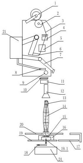
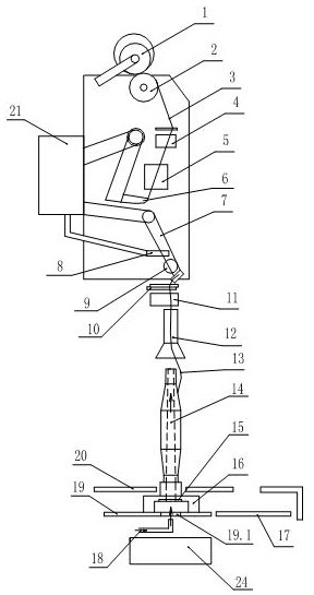
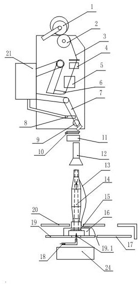
[0037] see Figure 5-Figure 6 , an embodiment of a tray-type bobbin winder of the present invention, comprising a single bobbin of the bobbin winder and a bobbin processing device, wherein the single bobbin of the bobbin winder includes a pipe changing device, a negative pressure box 21, a compressed air blowing nozzle 18 and its For the air supply system, a compressed air blow nozzle 18 is arranged below the single spindle unwinding station of the tube changing device, and the compressed air blow nozzle 18 is connected to the air supply system through an air supply pipeline. A negative pressure suction head 22 is set at the single ingot unwinding station, an air inlet and an air outlet are set on the negative pressure suction head 22, the air inlet of the negative pressure suction head 22 is close to the air outlet of the compressed air blow nozzle 18, and the negativ...


PUM


Abstract

The invention provides a tray-type winding machine and a winding production method. The tray-type winding machine comprises a winding machine single spindle and a bobbin yarn processing device, wherein the winding machine single spindle comprises a tube changing device, a negative pressure box, a compressed air blowing nozzle and an air supply system; and the compressed air blowing nozzle is arranged below a single spindle unwinding station of the tube changing device, and is connected to the air supply system through an air supply pipeline. The tray-type winding machine is characterized in that a negative pressure suction head is arranged below the single spindle unwinding station; an air inlet of the negative pressure suction head is close to an air outlet of the compressed air blowing nozzle; the air suction direction of the air inlet of the negative pressure suction head is opposite to the air blowing direction of the air outlet of the compressed air blowing nozzle; and an air outlet of the negative pressure suction head is connected to the negative pressure box. When a small suction nozzle fails to grasp the head of the bobbin yarn to cause the falling of the head of the bobbin yarn, the head of the bobbin yarn can automatically enter a center hole of the bobbin yarn for secondary threading, or returns to the bobbin yarn processing device for secondary threading, thus, thewasting caused by hard waste winding is avoided, and the maintenance workload is reduced. The tray-type winding machine has a simple structure and low cost and is convenient to install and transform.The single spindle bobbin yarn threading method is simple, is reliable for threading, and has high efficiency.

Description

technical field [0001] The invention belongs to the technical field of textile machinery manufacturing, and relates to the improvement of an automatic winding machine and a winding production method, in particular to a tray type winding machine and a winding production method. Background technique [0002] In the existing tray-type winding machine, the bobbin supply of a single spindle is conveyed by the bobbin tray through a flat belt. During the unwinding process of a single spindle, when the yarn clearer cuts the yarn or replaces a new bobbin, The small suction nozzle will go down to absorb the yarn end cut by the scissors below, but in some cases (the resistance of the small suction nozzle is large or the small suction nozzle is partially blocked), the small suction nozzle does not suck the yarn end, and the bobbin yarn The bobbin will fall off. At this time, a new bobbin can only be replaced, and the bobbin that has fallen off the bobbin end is discharged onto the flat ...

Claims


Application Information

Patent Timeline
Patent Type & Authority Applications(China)
IPC IPC(8): B65H54/70B65H54/86B65H49/26
CPCB65H54/707B65H54/702B65H54/70B65H54/86B65H49/26B65H67/083B65H2701/31
Inventor 车社海国世光路枫澄刘晓良
Owner QINGDAO HONGDA TEXTILE MACHINERY
Learn More