Highly directional plano-concave lens with non-uniform thickness enz metamaterial sandwich layer

A plano-concave lens and metamaterial technology, applied in antennas, electrical components, etc., can solve the problems of difficult impedance matching, complex lens antenna design structure, etc., and achieve the effects of fewer devices, low cost, and easy processing.

Active Publication Date: 2021-05-04
XIDIAN UNIV
View PDF12 Cites 0 Cited by
  • Summary
  • Abstract
  • Description
  • Claims
  • Application Information

AI Technical Summary

Problems solved by technology

[0006] The purpose of the present invention is to solve the problems existing in the above-mentioned prior art, and provide a highly directional plano-concave lens containing an ENZ supermaterial sandwich layer with a non-uniform thickness, which is used to solve the complex design structure of the lens antenna in the prior art and the difficulty in achieving impedance matching bigger problem

Method used


Image

  • Highly directional plano-concave lens with non-uniform thickness enz metamaterial sandwich layer
  • Highly directional plano-concave lens with non-uniform thickness enz metamaterial sandwich layer
  • Highly directional plano-concave lens with non-uniform thickness enz metamaterial sandwich layer

Examples


Embodiment 1

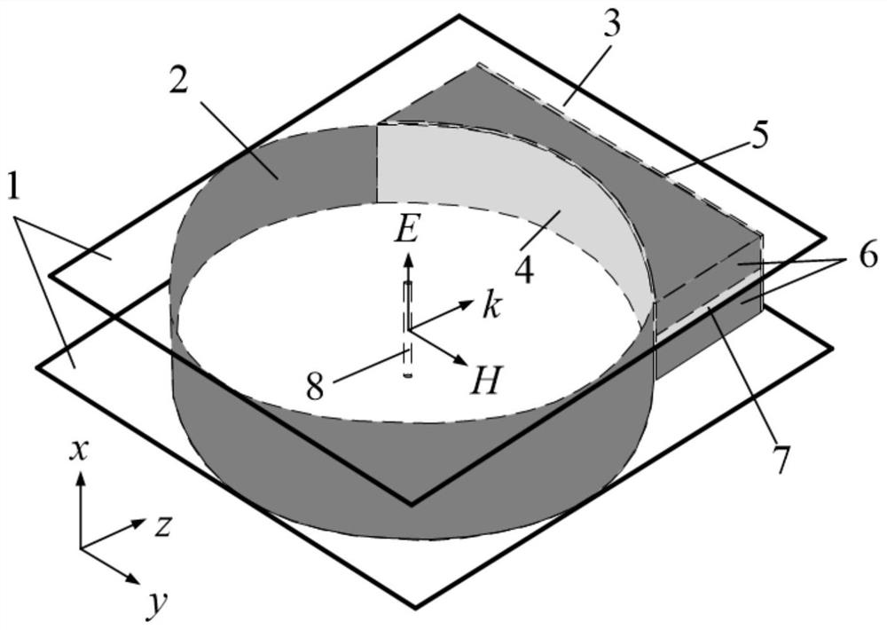
[0037] Example 1, a highly directional plano-concave lens with a non-uniform thickness ENZ metamaterial sandwich layer with a working frequency of 67 GHz.

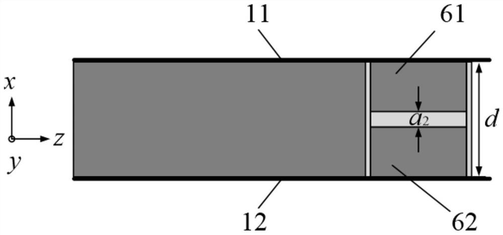
[0038] The embodiment of the present invention includes: the metal reflective surface 2 of equal height and the flat-concave lens 3 are arranged in the upper metal plate 11 and the lower metal plate 12 of the parallel plate waveguide 1, and the height d=20mm. The metal reflective surface 2 and the upper metal plate 11 and the lower metal plate 12 of the parallel plate waveguide 1 have a thickness of 0.1 mm, the metal reflective surface 2 and the flat-convex lens 3 form a closed circle, and the metal reflective surface accounts for three quarters of the closed circle. The plano-concave lens occupies a quarter of the closed circle, and the radius of the closed circle is r=31.66mm. The incident surface of the plano-concave lens 3 is a concave surface, the outgoing surface is a plane, and the length of the long side of the out...

Embodiment 2

[0039] Example 2, a highly directional plano-concave lens with a non-uniform thickness ENZ metamaterial sandwich layer with a working frequency of 92.5 GHz.

[0040] The structure of the embodiment of the present invention is the same as that of Embodiment 1, and the height d of the metal reflective surface 2 and the plano-concave lens 3, the thickness of the metal reflective surface 2 and the upper metal plate 11 and the lower metal plate 12 of the parallel plate waveguide 1, the metal plate The minimum width t of the upper metal plate 61 of 6 1 , the thickness l of the concave ENZ metamaterial substrate 4 and the planar ENZ metamaterial substrate 5, the dielectric constant ε of the ENZ metamaterial r and permeability μ r , and in the formula for calculating a, the differential characteristic admittance Y of free space 0 , differential length W 1 These parameters remain unchanged, only the following parameters have been changed:

[0041] The radius r=22.93mm of the closed...


PUM

PropertyMeasurementUnit
thicknessaaaaaaaaaa

Abstract

A highly directional plano-concave lens containing a non-uniform thickness ENZ supermaterial sandwich layer, including a parallel slab waveguide, a metal reflective surface and a plano-concave lens, and the metal reflective surface and plano-concave lens are placed in the parallel slab waveguide as a whole, accounting for three quarters The metal reflective surface and a quarter of the plano-concave lens form a closed circle. The plano-concave lens is composed of a concave ENZ metamaterial substrate, an intermediate layer and a planar ENZ metamaterial substrate, and a concave ENZ metamaterial substrate and a planar ENZ metamaterial substrate. The thickness is l, and the middle layer is composed of a metal plate with equal width and an ENZ metamaterial interlayer that is closely attached between the symmetrical upper and lower metal plates. The thickness a of the ENZ metamaterial interlayer increases with the width t of the metal plate. Presenting non-uniform changes with nonlinear reduction, the line source is set at the center of the closed circle and parallel to the short side of the exit surface of the plano-concave lens.

Description

technical field [0001] The invention belongs to the technical field of electronic devices, and further relates to a highly directional plano-concave lens containing a sandwich layer of ENZ (epsilon-near-zero) supermaterial with non-uniform thickness and dielectric constant tending to zero in the technical field of microwave devices. The invention can be used for efficient transmission and directional radiation of line source electromagnetic waves. [0002] technical background [0003] In the fields of satellite communication and radar systems, antennas with high gain and low sidelobe have been widely used, while metamaterial lens antennas have the advantages of high directivity, small sidelobe and backlobe, etc., and have been widely used in microwave engineering, communication and military fields. being widely used. Usually, metamaterial lens antennas use artificial electromagnetic metamaterial units of different sizes arranged regularly to obtain the graded refractive ind...

Claims


Application Information

Patent Timeline
Patent Type & Authority Patents(China)
IPC IPC(8): H01Q15/00H01Q15/12
CPCH01Q15/0086H01Q15/12
Inventor 杨锐贾艺铭雷振亚
Owner XIDIAN UNIV
Why Eureka
Try Eureka