
Multi-antenna network receiving equipment applied to remote communication of power system

A technology for long-distance communication and receiving equipment, which is applied in radio transmission systems, diversity/multi-antenna systems, and structural parts of electrical equipment, etc. It can solve problems such as high module temperature, short circuit or fire, insufficient cable diameter or flame retardancy, etc. , to achieve the effect of reducing product volume, saving input cost and improving heat dissipation effect

Pending Publication Date: 2020-11-06
FOSHAN POWER SUPPLY BUREAU GUANGDONG POWER GRID
View PDF4 Cites 0 Cited by
  • Summary
  • Abstract
  • Description
  • Claims
  • Application Information

AI Technical Summary

Problems solved by technology

[0003] However, the equipment communication network has always been the bottleneck that plagues the automation construction and development of power equipment. At present, most of the more mature and stable antenna network receiving equipment in the market only connect to one antenna, and the higher-end ones can also connect to three antennas. Commonly used antennas mainly include point-to-point Parabolic antennas, directional antennas with 60° coverage and 360° omnidirectional antennas and other types of antennas; multiple frequencies in these antennas include 2.4G frequency and 5.8G frequency; it is impossible to connect and communicate with compatible two frequency bands, and the device is tightly installed , large instantaneous current, insufficient cable diameter or flame retardant performance, may cause the module temperature to be too high, and may even cause serious accidents such as short circuit or fire
It is difficult to meet the current goal of equipment automation construction in electric power enterprises

Method used


Image

  • Multi-antenna network receiving equipment applied to remote communication of power system
  • Multi-antenna network receiving equipment applied to remote communication of power system
  • Multi-antenna network receiving equipment applied to remote communication of power system

Examples


Embodiment 1

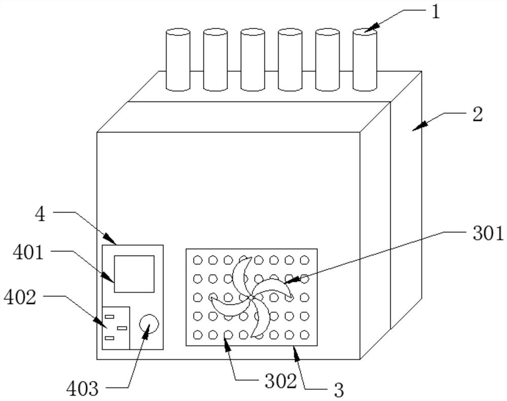
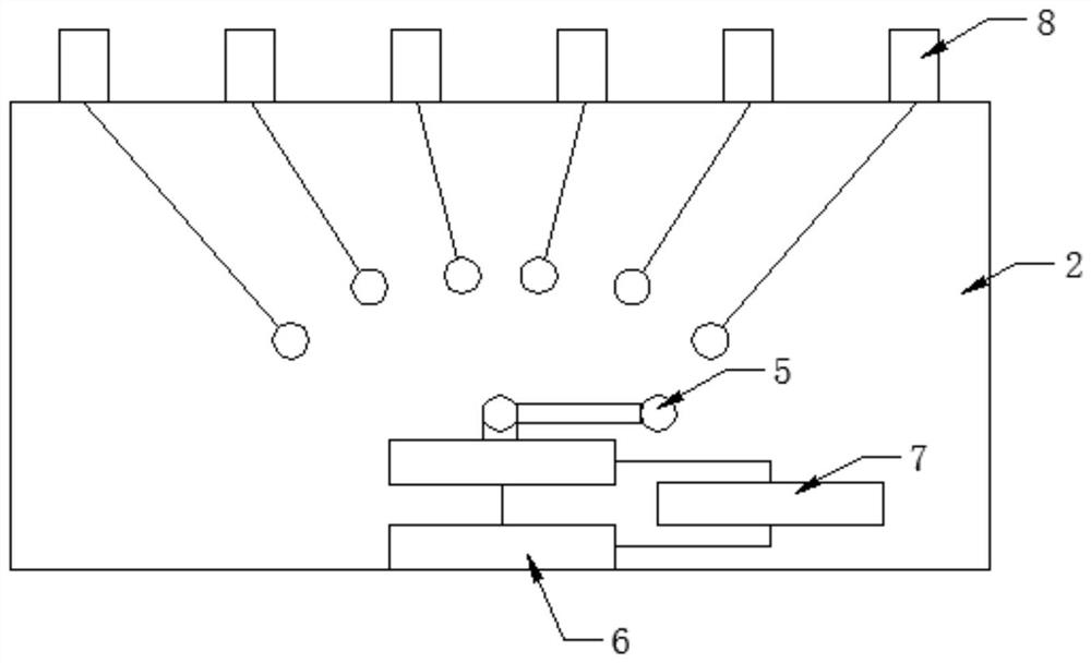
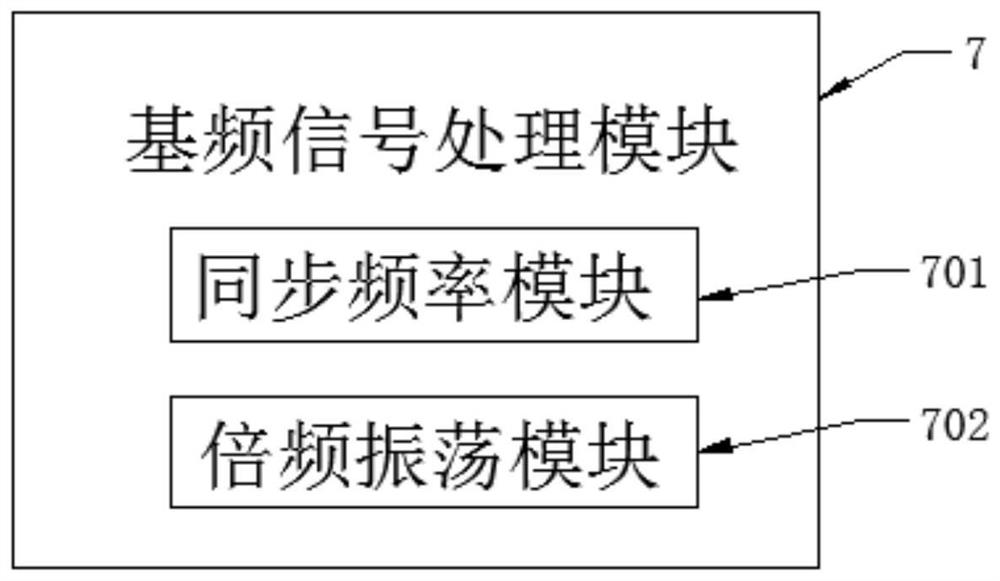
[0025] see Figure 1-4 , the present invention provides a technical solution: a multi-antenna network receiving device applied to electric power system remote communication, including a plurality of antennas 1, a multi-antenna switching module 2, a heat dissipation module 3 and a power supply module 4; the multi-antenna switching module 2 It is composed of a plurality of antenna interfaces 8, an antenna switch 5, a single-chip microcomputer 6 and a baseband signal processing module 7. The heat dissipation module 3 is composed of a heat dissipation hole 302 and a fan 301. The power supply module 4 is composed of a power socket 402, a power supply Composed of a switch 401 and a module indicator light 403.

[0026] In this embodiment, in the multi-antenna switching module 2, a plurality of antenna interfaces 8 are used for wired connection with a plurality of antennas 1 through antenna 1 cables; a plurality of antennas 1 may include but not limited to: point-to-point parabolic an...

Embodiment 2

[0035] Such as Figure 4 As shown, the method of using the multi-antenna network receiving device also includes: the antenna switching switch 5 is switched to the contact of the antenna interface 8 to be connected according to the wireless signal received by the single-chip microcomputer 6,

[0036] For example, a point-to-point parabolic antenna sends a signal to the network receiving device, and the network receiving device recognizes the signal type through the single-chip microcomputer 6, and switches the antenna corresponding to the antenna through the antenna switch 5 for signal transmission.

[0037] Or multiple antennas 1 transmit the received wireless signals to the baseband signal processing module 7 of the multi-antenna switching module 2, and the baseband signal processing module 7 processes the received wireless signals as baseband signals and transmits them to the receiving antenna 1 .

[0038] For example, a point-to-point parabolic antenna sends a signal to th...


PUM


Abstract

The invention discloses multi-antenna network receiving equipment applied to remote communication of a power system in the technical field of power network systems. The multi-antenna network receivingequipment comprises a plurality of antennas, a multi-antenna switching module, a heat dissipation module and a power module. The multi-antenna switching module is composed of a plurality of antenna interfaces, an antenna change-over switch, a single-chip microcomputer and a fundamental frequency signal processing module. The heat dissipation module is composed of heat dissipation holes and a fan.The power module is composed of a power socket, a power switch and a module indicator lamp. The integration level is high, the product size is greatly reduced, the heat dissipation module is newly added, and the heat dissipation effect of the controller is improved. A plurality of antenna interfaces are arranged, so that a plurality of antennas can be integrated at the same time, the antennas ofdifferent types can be connected to the same transceiver to adapt to different application environments, signal communication between antennas of the same type can be achieved, fundamental frequency processing can be conducted through the fundamental frequency signal processing module to realize signal communication between antennas of different types, and a large amount of investment cost can besaved.

Description

technical field [0001] The invention relates to the technical field of electric power network systems, in particular to a multi-antenna network receiving device applied to electric power system remote communication. Background technique [0002] There are many distribution points and a wide area of ​​power distribution lines. Some equipments are located in harsh environments, and failures caused by micro-climate and special sections occur from time to time. The equipment is densely distributed and shielded from each other, and many parts cannot be inspected live; therefore, through the development of flexible on-site video acquisition technology (device), temperature detection and intelligent distribution network line status monitoring system, the obtained on-site video, key point temperature, etc. The data is uploaded to the main station platform in real time to achieve unified visual management, thereby shortening the response and processing time of line faults, playing th...

Claims


Application Information

Patent Timeline
Patent Type & Authority Applications(China)
IPC IPC(8): H04B7/08H05K7/20
CPCH04B7/0805H04B7/0874H05K7/20136
Inventor 刘石生黎颖茵陈建文曹宏宇冷剑刘志雄郭宏波黄伟何通郑剑锋蔡冠华钱志生王健祥莫有光叶梓明岑添云程志秋邓铭元邝展
Owner FOSHAN POWER SUPPLY BUREAU GUANGDONG POWER GRID
Learn More