
Low-pressure oil-water well under-pressure well repairing device and under-pressure well repairing method

A low-pressure oil and workover technology, applied in wellbore/well components, drilling equipment, earth-moving drilling, etc., can solve the problems of short service life of annular blowout preventer rubber core, deterioration of construction environment, high procurement cost, etc. The effect of shortening the workover and well stop time, facilitating the operation of opening and closing the well, and shortening the installation time

Active Publication Date: 2020-11-10
CHINA PETROLEUM & CHEM CORP +1
View PDF7 Cites 4 Cited by
  • Summary
  • Abstract
  • Description
  • Claims
  • Application Information

AI Technical Summary

Problems solved by technology

[0003] 1. In order to realize high-pressure sealing construction, multiple semi-sealed BOPs, full-sealed BOPs or annular BOPs are usually installed. There are many structural components, and the height is mostly above 5m. The overall height is too high, the installation is complicated, and the operation is inconvenient. , poor safety, and the relocation of the whole machine is inflexible and low in efficiency. For low-pressure wells, there is a problem of inefficiency of "big horse-drawn carts". At present, there is no small-scale workover device for low-pressure wells with a height of no more than 2m in the oil field
[0004] 2. When the well pressure is low and there will be no oil pipe topping phenomenon, in order to improve the construction progress, the annular blowout preventer is usually used to seal the oil pipe annulus when lifting and lowering the oil pipe, resulting in a short service life of the annular blowout preventer rubber core. The rubber core of the blowout preventer is frequently replaced, and the purchase cost is high
[0005] 3. During the routine operation of oil-water wells with pressurized workover and small overflow wells, the overflow between the outer periphery of the tubing and the blowout preventer due to the lack of sealing, and the overflow of liquid in the tubing will bring serious pollution to the well site; During the process of lifting the oil pipe, when the oil pipe is blocked or there is no oil drain device at the lower part, when the connecting thread of the oil pipe is removed, the liquid in the oil pipe will flow down quickly, and the dirty oil and water will fall and splash on the flange of the blowout preventer plane, causing environmental pollution at the wellhead, deterioration of the construction environment, and affecting the physical and mental health of operators
Existing high-pressure operation devices do not have the function of overflow collection. Under the circumstances of increasing environmental protection requirements, how to realize the function of not affecting the operation speed and avoiding the well site from being polluted by overflow has always been a problem that plagues underground operations.

Method used


Image

  • Low-pressure oil-water well under-pressure well repairing device and under-pressure well repairing method
  • Low-pressure oil-water well under-pressure well repairing device and under-pressure well repairing method
  • Low-pressure oil-water well under-pressure well repairing device and under-pressure well repairing method

Examples


Embodiment Construction

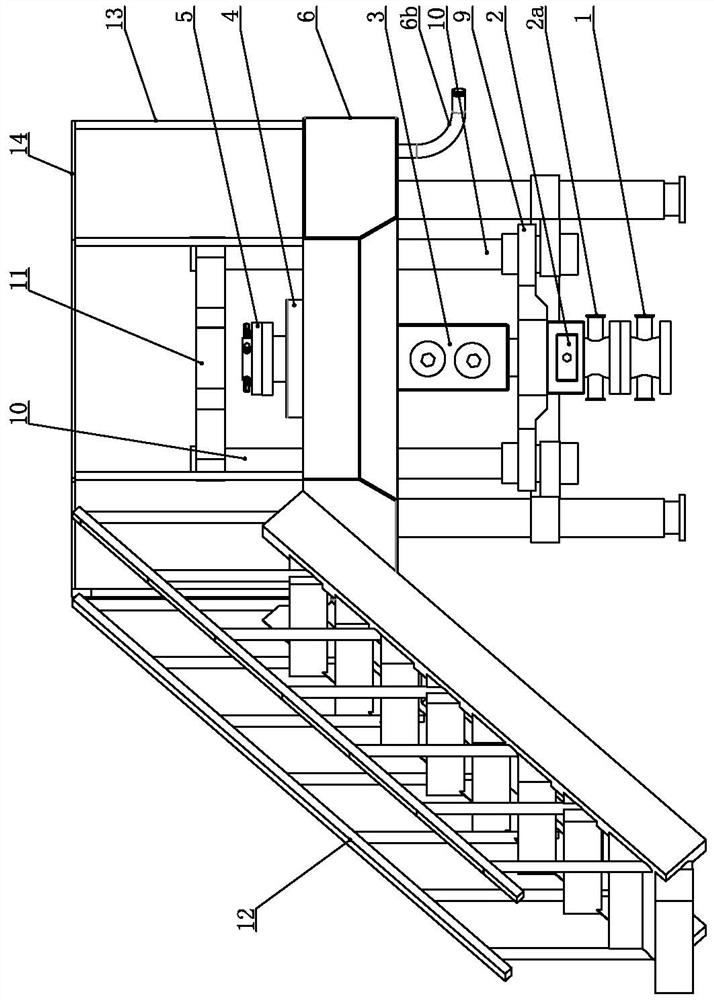
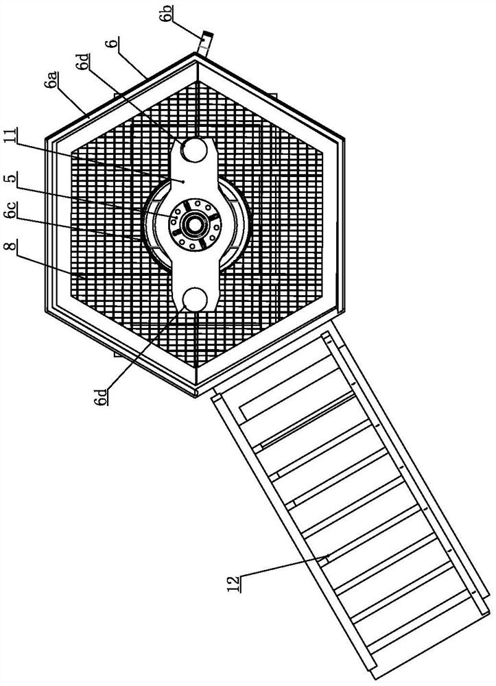
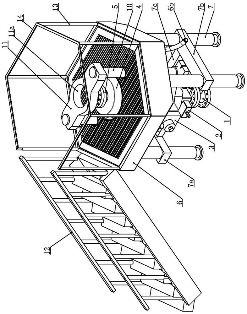
[0035] Such as Figure 1 to Figure 8 As shown, the pressurized workover device for low-pressure oil-water wells of the present invention includes a single ram blowout preventer 2 installed above the wellhead cross 1, the bottom of the single ram blowout preventer 2 has a cross, and the single ram preventer A double ram slip BOP 3 is installed above the injector 2, an annular BOP 4 is installed above the double ram slip BOP 3, and a hexagonal grid platform is installed on the outer periphery of the middle section of the annular BOP 4 8. A sunken collection box 6 is provided below the hexagonal grid platform 8. The bottom of the sunken collection box 6 is supported on the ground by four rectangularly distributed outriggers 7, and the bottom edge of the sunken collection box 6 A discharge elbow 6b is connected.

[0036] The hexagonal grid platform 8 can provide an operating platform for workers. The overflow during wellhead operation can flow into the sinking collection box 6. A...


PUM


Abstract

The invention relates to a low-pressure oil-water well under-pressure well repairing device and an under-pressure well repairing method. A blowout preventer set is installed on an upper flange of a wellhead four-way joint through bolts and sequentially comprises a single-gate-plate blowout preventer, a double-gate-plate slip blowout preventer and an annular blowout preventer from bottom to top, afour-way joint is arranged at the lower portion of the single-gate-plate blowout preventer, the double-gate-plate slip blowout preventer is installed above the single-gate-plate blowout preventer, theannular blowout preventer is installed above the double-gate-plate slip blowout preventer, a hexagonal grid platform is arranged at the periphery of the middle section of the annular blowout preventer, and a sunken collecting box is arranged below the hexagonal grid platform; the bottom of the sunken collecting box is supported on the ground through four supporting legs distributed in a rectangular shape, and the edge of the bottom of the sunken collecting box is connected with a discharging bent pipe; the lower middle part of the annular blowout preventer is positioned in a central cylinder;lifting hydraulic cylinders are installed at the two ends of a lower cross beam correspondingly and vertically penetrate through sleeves upwards to be connected with an upper cross beam; and before operation, the blowout preventer set is connected in advance, the under-pressure well repairing device is installed, and a tubing string is pulled out. By means of the low-pressure oil-water well under-pressure well repairing device and the under-pressure well repairing method, the well mouth environment can be improved, the height is low, overall moving is facilitated, and the installation time isgreatly shortened.

Description

technical field [0001] The invention relates to an oilfield operation tool, in particular to a workover device for a low-pressure oil-water well under pressure; the invention also relates to a workover method for a low-pressure oil-water well under pressure, belonging to the technical field of workover under pressure. Background technique [0002] The wellhead device of the oil-water well includes the wellhead spool and various blowout preventers installed above the wellhead spool, and the oil pipe extends along the center of each blowout preventer. At present, the downhole pressure of oil and water wells in oil fields can be classified into three types: high, medium and low, among which low pressure wells account for a relatively high proportion. However, most of the workover devices for oil and water wells in oil fields are high-pressure operation devices, which have the following deficiencies: [0003] 1. In order to realize high-pressure sealing construction, multiple s...

Claims


Application Information

Patent Timeline
Patent Type & Authority Applications(China)
IPC IPC(8): E21B19/00E21B33/06E21B33/08E21B19/14
CPCE21B19/00E21B33/06E21B33/08E21B19/14
Inventor 刘海明钱红彬乔春国
Owner CHINA PETROLEUM & CHEM CORP
Learn More