Probe for tobacco quality spectrum detection

A spectrum and tobacco leaf technology, applied in the field of infrared spectrum detection, can solve the problems of increasing the risk of contact with the liquid to be measured, the surface of the lens being exposed, and being easily collided. Effect

Inactive Publication Date: 2020-11-10
NANKAI UNIV
View PDF0 Cites 3 Cited by
  • Summary
  • Abstract
  • Description
  • Claims
  • Application Information

AI Technical Summary

Problems solved by technology

However, this method makes the lens protrude. On the one hand, it is easy to expose the surface of the lens, and it is easy to be damaged by collision, thus affecting the imaging; on the other hand, when the liquid is detected, the probe should be as compatible with the liquid to be measured Proximity, which increases the risk of contact with the liquid to be tested

Method used


Image

  • Probe for tobacco quality spectrum detection
  • Probe for tobacco quality spectrum detection
  • Probe for tobacco quality spectrum detection

Examples


Embodiment 1

[0024] The parameters of each optical lens in this embodiment are shown in Table 1.

[0025]

[0026]

[0027] Table 1

[0028] Among them, the meaning of each symbol is as follows:

[0029] S1: Entrance pupil position

[0030] R1: radius of curvature of the object side surface of the first lens L1;

[0031] R2: radius of curvature of the image side of the first lens L1;

[0032] R3: radius of curvature of the object side surface of the second lens L2;

[0033] R4: radius of curvature of the image side of the second lens L2;

[0034] R5: radius of curvature of the object side surface of the third lens L3;

[0035] R6: radius of curvature of the image side of the third lens L3;

[0036] R7: the radius of curvature of the object side of the fourth lens (cemented lens) L4;

[0037] R8: the radius of curvature of the image side of the fourth lens (cemented lens) L4;

[0038] R9: the radius of curvature of the image side of the fifth lens (cemented lens) L5;

[0039]...

Embodiment 2

[0085] The parameters of each optical lens in this embodiment are shown in Table 3.

[0086]

[0087]

[0088] table 3

[0089] The meanings of the letters used in Table 3 are the same as in Example 1.

[0090] The third lens is an aspheric lens, and its aspheric coefficients are shown in the table below:

[0091]

[0092] Table 4

[0093] In this embodiment, the first lens L1, the second lens L2, the third lens L3, the fourth lens L4, the fifth lens L5, the sixth lens L6, the seventh lens L7, The eighth lens L8, the ninth lens L9, the tenth lens L10, and the eleventh lens L11; wherein the third lens is an aspheric lens.

[0094] According to the aspherical image height formula:

[0095]

[0096] Where k is the conic coefficient, for the surface R5, K5 = 1.418; for the surface R6, K6 = 1.134. A4, A6, A8, A10, A12, A14, A16 are aspheric coefficients.

[0097] The equivalent focal length of the optical system is f=1.521cm. The object side of the first lens is ...

Embodiment 3

[0101] The parameters of each optical lens in this embodiment are shown in Table 5.

[0102]

[0103]

[0104] table 5

[0105] The third lens is an aspheric lens, and its aspheric coefficients are shown in Table 6:

[0106]

[0107] Table 6

[0108] According to the aspherical image height formula:

[0109]

[0110] Wherein k is the conic coefficient, for the surface R5, K5=1.538; for the surface R6, K6=1.170. A4, A6, A8, A10, A12, A14, A16 are aspheric coefficients.

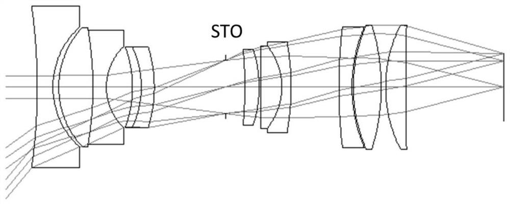
[0111] The equivalent focal length of the optical system is f=1.473cm. The object side of the first lens is a concave surface, the focal power of the first lens is set to be negative, and its focal length f1=-1.184cm; Set the focal power of the third lens to be negative, and its focal length f3=-1.926cm, Set the distance D9=1.104cm between the aperture STO of the probe optical system and the image side of the fifth lens L5; the distance D10=0.321cm between the aperture STO and the object s...


PUM


Abstract

A tobacco spectrum special probe optical system is sequentially composed of a first lens, a second lens, a third lens, a fourth lens, a fifth lens, a sixth lens, a seventh lens, an eighth lens, a ninth lens, a tenth lens and an eleventh lens in the optical axis direction, wherein the first lens and the third lens are negative focal power lenses. The system satisfies the conditions that the equivalent focal length of the optical system of the probe is f; the focal length of the first lens is f1; the focal length of the third lens is f3; D9 is the distance between an aperture STO of the opticalsystem and the image side of the fifth lens on the optical axis; and D10 is the distance D10 between the aperture STO and the object side of the sixth lens L6. According to the optical system, the spectral imaging of near-infrared light is effectively improved, and meanwhile, the effective focal length of the optical system is reduced; the object side surface of the first lens is arranged to be aconcave surface, so that unnecessary contact with a to-be-measured object can be avoided.

Description

[0001] field of invention [0002] The invention relates to the field of infrared spectrum detection, in particular to an optical probe structure specially used for tobacco leaf quality spectrum. Background technique [0003] The optical probes currently used are not optimized for the application field, especially the possible spectral characteristic peaks. In order to meet the needs of multi-band detection, the optical probes often do not have special features for a certain band from ultraviolet to infrared light. Optimized processing. And if it is not optimized for a certain wavelength band, it will bring a large chromatic aberration to the optical system. For example, when the probe light is visible light and infrared light, due to the large difference in wavelength, the chromatic aberration is also large; the result is blurred imaging at the focal plane, resulting in a decrease in imaging resolution. Most of the existing detection probes are used for both imaging spectru...

Claims


Application Information

Patent Timeline
Patent Type & Authority Applications(China)
IPC IPC(8): G02B13/00G02B13/14G02B13/18G01J3/28G01J3/02G01N21/3563G01N21/359
CPCG01J3/0205G01J3/2823G01J2003/2826G01N21/35G02B13/0045G02B13/008G02B13/14G02B13/18
Inventor 王斌徐晓轩张月颖张文杰
Owner NANKAI UNIV
Why Eureka
Try Eureka