
Machining equipment facilitating waste collection and used for drilling of inner cavity of LED lamp protective cover

A technology of LED lights and waste collection, applied in metal processing equipment, drilling/drilling equipment, boring/drilling, etc., can solve problems such as falling into drilling equipment, troublesome cleaning in the later stage, and machine jamming, etc., to achieve Easy to clean and good for work efficiency

Inactive Publication Date: 2020-11-17
重庆数智源智能装备科技有限公司
View PDF0 Cites 1 Cited by
  • Summary
  • Abstract
  • Description
  • Claims
  • Application Information

AI Technical Summary

Problems solved by technology

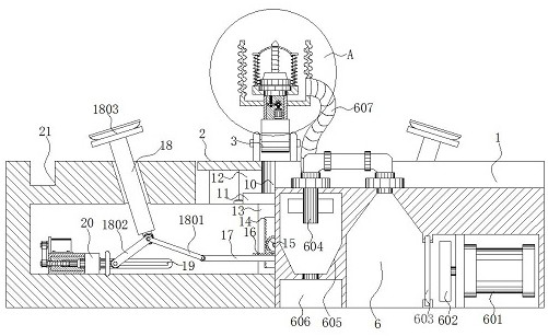
[0004] The purpose of the present invention is to provide a kind of processing equipment for drilling the inner cavity of the protective cover of LED lamps, which is convenient for collecting waste materials, so as to solve the problem in the above-mentioned background technology that when drilling inside the protective cover, there is no cleaning in time, resulting in residues during processing. Chips and slag are flying all over the sky, thus falling onto the drilling equipment. As time goes on, it is easy to cause the machine to freeze, and it is also very troublesome for later cleaning.

Method used


Image

  • Machining equipment facilitating waste collection and used for drilling of inner cavity of LED lamp protective cover
  • Machining equipment facilitating waste collection and used for drilling of inner cavity of LED lamp protective cover
  • Machining equipment facilitating waste collection and used for drilling of inner cavity of LED lamp protective cover

Examples


Embodiment Construction

[0027] The technical solutions in the embodiments of the present invention will be clearly and completely described below in conjunction with the accompanying drawings in the embodiments of the present invention. Obviously, the described embodiments are only some of the embodiments of the present invention, not all of them. Based on The embodiments of the present invention and all other embodiments obtained by persons of ordinary skill in the art without making creative efforts belong to the protection scope of the present invention.

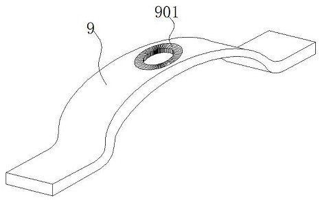
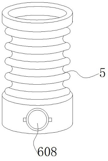
[0028] see Figure 1-5, the present invention provides a technical solution: a kind of processing equipment for drilling the inner cavity of the LED lamp protective cover to facilitate waste collection, including a collection box 1, a workbench 2 is provided at the middle groove of the upper surface of the collection box 1, and the working A rotating arm 3 is installed in the upper middle part of the platform 2, and a drilling mechanism 4 is arr...


PUM


Abstract

The invention discloses machining equipment facilitating waste collection and used for drilling of an inner cavity of an LED lamp protective cover. The machining equipment comprises a collecting box,a workbench is arranged in a groove in the middle of the upper surface of the collecting box, adsorption mechanisms are arranged at the outer side of the workbench and on the surface of the collectingbox in a manner of being symmetrical with respect to the center line, and clamping grooves are formed in the outer sides of the adsorption mechanisms and at the surface of the collecting box. According to the machining equipment, a drilling mechanism and a dust suction mechanism are arranged on the surface of the collecting box and in the collecting box correspondingly, and through the arrangement of a folding cover, the effect of being isolated from the outside is conveniently achieved when the interior of the LED protective cover is drilled through the drilling mechanism; and meanwhile, through the arrangement of the dust suction mechanism, waste chipping particles generated during drilling can be conveniently sucked away by the drilling mechanism, the phenomena of insufficient power and blockage caused by the fact that the waste chipping particles enter the drilling mechanism are avoided, and drilling of the LED dust cover is facilitated.

Description

technical field [0001] The invention relates to the technical field of LED lamp processing equipment, in particular to a processing equipment for drilling holes in the inner cavity of a protective cover of an LED lamp to facilitate waste collection. Background technique [0002] LED has a very obvious energy-saving advantage, and LED light is an electroluminescent semiconductor material chip, which is cured on the bracket with silver glue or white glue, and then connected to the chip and circuit board with silver or gold wires, surrounded by epoxy It is sealed with resin to protect the inner core wire, and finally the shell is installed, so the LED light has good shock resistance. With the development of the times, the color of LED light is more and more, so people use it in outdoor light shows and light tube reminders. more and more. [0003] With the development of the times, there are more and more people's night activities. The elderly go to the park to dance square dan...

Claims


Application Information

Patent Timeline
Patent Type & Authority Applications(China)
IPC IPC(8): B23B41/00B23B47/00B23Q3/08B23Q11/00B23Q11/08B08B1/00
CPCB23B41/00B23B47/00B23Q3/088B23Q11/0046B23Q11/0042B23Q11/08B08B1/12
Inventor 李勇罗星
Owner 重庆数智源智能装备科技有限公司
Learn More