Coarse aggregate for foam concrete and production device thereof
A foamed concrete and production device technology, which is applied to clay preparation devices, raw material supply devices for sale, cement mixing devices, etc., can solve the problems of affecting the mechanical properties of foamed concrete, different diameters of foams, uneven distribution of foams, etc. Resource consumption, improve comprehensive mechanical properties, strength and good waterproof effect
- Summary
- Abstract
- Description
- Claims
- Application Information
AI Technical Summary
Problems solved by technology
Method used
Image

Examples
Embodiment 1
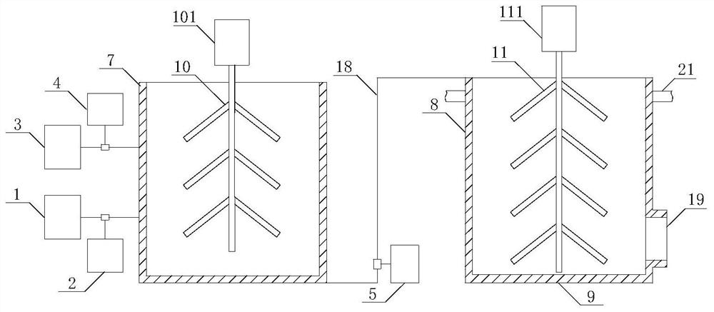
[0042] A production device for coarse aggregate for foamed concrete, comprising: a foamed cement slurry preparation system, a filling system and a PLC controller, see figure 1 , the foamed cement slurry preparation system and the filling system are communicated through a delivery pipe 18, and the foamed cement slurry preparation system includes a water tank 1, a water pump 2, a foaming agent bucket 3, a foaming agent pump 4, a cement slurry mixing tank 7 and a set In the cement slurry high-speed mixer 10 inside the cement slurry mixing tank 7, the power source of the cement slurry high-speed mixer 10 is a first motor 101, and the first motor 101 is located on the top of the cement slurry mixing tank 7; the water pump 2 For pumping the water in the water tank 1 to the cement slurry mixing tank 7, the foaming agent pump 4 is used to pump the foaming agent in the foaming agent barrel 3 to the cement slurry mixing tank 7, and the cement slurry mixing The tank 7 is connected to one...
Embodiment 2
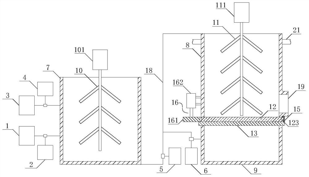
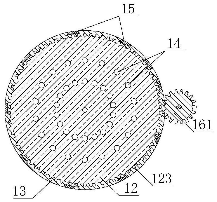
[0046] Embodiment 2 is basically the same as Embodiment 1, and its difference is: see figure 2 and image 3 , the filling system also includes a cement slurry recovery pump 6 and a cement slurry recovery bin 9, the cement slurry recovery bin 9 is an open top structure, and the top of the cement slurry recovery bin 9 is connected to the hollow material mixing tank 8 The bottom of the hollow material mixing tank 8 is sealed through the bottom of the hollow material mixing tank 8. The cement slurry recovery bin 9 communicates with the hollow material mixing tank 8 through a delivery pipe 18. The bottom of the hollow material mixing tank 8 includes a two-layer structure , are respectively the upper bottom plate 12 and the lower bottom plate 13, the lower bottom plate 13 is fixedly connected with the tank wall of the hollow material mixing tank 8, specifically, the lower bottom plate 13 is fixedly provided with an L-shaped connecting plate 15, so The other end of the connecting p...
Embodiment 3
[0050] Embodiment 3 is basically the same as Embodiment 2, the difference is: see Figure 4 and Figure 5 , the upper end of the upper bottom plate 12 is provided with an annular groove 121, the annular groove 121 is matched with the positioning boss of the hollow material mixing tank 8, and the lower end of the upper bottom plate 12 is provided with an annular boss 122, The annular boss 122 cooperates with the positioning groove of the lower bottom plate 13, and through mutual cooperation, the positions of the tank wall, the upper bottom plate 12, and the lower bottom plate 13 of the hollow material mixing tank 8 can be aligned and locked, During the rotation process of the upper base plate 12, there is no dislocation and no sliding, which is beneficial to the stability of the upper base plate 12 rotation.
PUM
| Property | Measurement | Unit |
|---|---|---|
| Particle size | aaaaa | aaaaa |
Abstract
Description
Claims
Application Information
 - R&D
- Intellectual Property
- Life Sciences
- Materials
- Tech Scout
- Unparalleled Data Quality
- Higher Quality Content
- 60% Fewer Hallucinations
Browse by: Latest US Patents, China's latest patents, Technical Efficacy Thesaurus, Application Domain, Technology Topic, Popular Technical Reports.
© 2025 PatSnap. All rights reserved.Legal|Privacy policy|Modern Slavery Act Transparency Statement|Sitemap|About US| Contact US: help@patsnap.com