Air conditioning system and exhaust control method thereof

A technology of an air conditioning system and a control method, which is applied in the field of air conditioning, can solve the problems of limited cooling effect of heating devices and can not solve the problem of cooling and heat dissipation of driving modules, and achieves the effect of avoiding local high temperature indoors, improving the utilization rate of cooling capacity, and simplifying the structure.

Inactive Publication Date: 2020-11-17
GREE ELECTRIC APPLIANCES INC
View PDF8 Cites 1 Cited by
  • Summary
  • Abstract
  • Description
  • Claims
  • Application Information

AI Technical Summary

Problems solved by technology

[0006] However, when the outdoor air temperature is high, the indoor cold air introduced to the indoor unit is easily exchanged quickly by the surrounding components. The indoor cold air drawn by this scheme has a limited cooling effect on the heat-generating components in the outdoor unit, and cannot solve the problem of outdoor air temperature. Cooling and heat dissipation problems of the driver module when it is high

Method used


Image

  • Air conditioning system and exhaust control method thereof
  • Air conditioning system and exhaust control method thereof
  • Air conditioning system and exhaust control method thereof

Examples


Embodiment 1

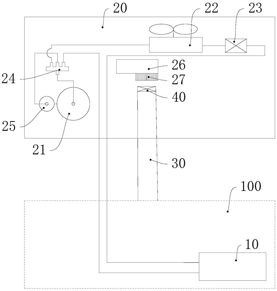
[0029] Please refer to figure 1 , the air conditioning system includes an indoor unit 10, an outdoor unit 20, a cold air pipe 30 and a first valve 40, and the outdoor unit 20 has a compressor 21, a condenser 22, a throttling device 23, a four-way valve 24, a liquid separator 25, a drive Module 26 (an example of a heating device) and cooling fan 27, the indoor unit 10 is arranged in the indoor environment 100, the indoor unit 10 has an evaporator (not shown in the figure), and the air outlet side of the cooling fan 27 faces the drive module 26 , one end of the cold air pipe 30 is connected to the indoor environment 100, the other end of the cold air pipe 30 is connected to the air intake side of the cooling fan 27, the first valve 40 is installed on the cold air pipe 30, and the first valve 40 is used to control the cooling air pipe 30 The pass and close.

[0030] The compressor 21, the condenser 22, the throttling device 23, the four-way valve 24, the liquid separator 25 and ...

Embodiment 2

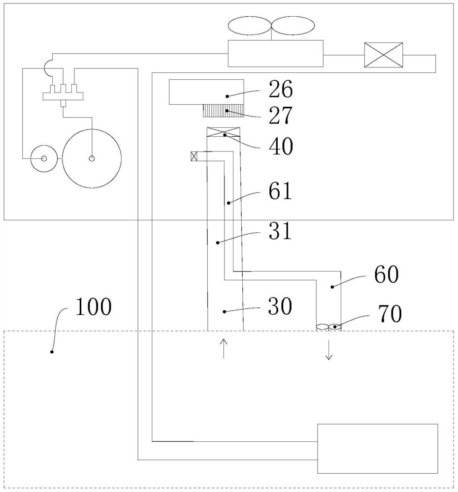
[0042] Please refer to Figure 4 , The air conditioning system of the present embodiment also includes an exhaust fan 50', and the exhaust fan 50' is installed at the air inlet end of the cold air duct 30'.

[0043] In Embodiment 1, in order to ensure that the cooling fan 27 can operate normally when the cold air pipe 30 is closed, the cold air pipe 30 cannot cover a large area of ​​the air intake side of the cooling fan 27, so when the cooling fan 27 is turned on and the first valve 40 is opened , the cooling fan 27 has a limited suction force for the air in the cold air duct 30, resulting in a limited flow of indoor cold air flowing to the cooling fan 27. Therefore, in this embodiment, an exhaust fan 50' is arranged on the cold air duct 30', which is conducive to passing through the exhaust fan 50. 'Agitating the indoor cold air to quickly flow to the cooling fan 27' and the driving module 26' further facilitates the rapid heat dissipation of the driving module 26'.

[0044...


PUM


Abstract

The invention relates to the field of air conditioners, and provides an air conditioning system and an exhaust control method thereof. The air conditioning system comprises an outdoor unit and a coldair pipe; the outdoor unit is provided with a heating device and a cooling fan; the air outlet side of the cooling fan faces the heating device; one end of the cold air pipe is used for communicatingwith indoor cold air; and the other end of the cold air pipe communicates with the air inlet side of the cooling fan. The cold air pipe communicates with the air inlet side of the cooling fan, so thatindoor cold air can be accurately guided to the cooling fan and the heating device, the cold energy of the indoor cold air is prevented from being consumed by other environmental devices, and the cold energy utilization rate of the indoor cold air is increased; moreover, when the cooling fan is in running, suction force can be formed for air in the cold air pipe; the cooling fan can be used for driving the indoor cold air to flow to the heating device at a relatively high speed, simplification of the structure of the air conditioning system can be facilitated, heat dissipation of the heatingdevice can be further accelerated through the indoor cold air flowing at a relatively high speed, and rapid heat dissipation of the heating device is further facilitated.

Description

technical field [0001] The invention relates to the field of air conditioning, in particular to an air conditioning system and an air exhaust control method thereof. Background technique [0002] The inverter air conditioner has a drive module, which tends to generate a lot of heat when it is running. When the temperature of the drive module is too high, the air conditioning system will control the compressor to reduce the operating frequency or even stop the compressor to reduce the heat generation of the drive module and avoid the drive module. Damaged by high temperature. [0003] In order to ensure that the air conditioning system can maintain normal function when the compressor is running at high frequency, the existing technology often installs a cooling device for the drive module. There are various cooling methods for the drive module. Common methods include setting a refrigerant branch circuit to cool the drive module. Or use a heat dissipation fan to blow air to a...

Claims


Application Information

Patent Timeline
Patent Type & Authority Applications(China)
IPC IPC(8): F24F1/06F24F1/24F24F1/38F24F11/32F24F11/64F24F11/871F24F140/40
CPCF24F1/06F24F1/24F24F1/38F24F11/32F24F11/64F24F11/871F24F2140/40
Inventor 晋鹏高阳冯绍广郭凯李捷
Owner GREE ELECTRIC APPLIANCES INC
Why Eureka
Try Eureka