Design method of optical fiber sensing ring of optical fiber current transformer based on 650nm waveband

A technology of fiber current and design method, applied in the directions of cladding fiber, optical waveguide light guide, voltage/current isolation, etc., can solve the problems of improved system accuracy, weakened linear birefringence suppression effect, uneven pitch, etc., and achieves low cost Effect

Active Publication Date: 2020-11-17
HARBIN INST OF TECH
View PDF5 Cites 0 Cited by
  • Summary
  • Abstract
  • Description
  • Claims
  • Application Information

AI Technical Summary

Problems solved by technology

However, there are still some problems with this fiber
First, the spin rate of the fiber stress filament is not uniform, which means that its pitch is also not uniform, which will cause residual linear birefringence in the fiber
Second, there is a huge stress in the fiber drawing process, which will cause changes in the photoelastic properties of the fiber core over time, which will gradually weaken the suppression effect of its linear birefringence
These problems in the optical fiber limit the further improvement of the system accuracy

Method used


Image

  • Design method of optical fiber sensing ring of optical fiber current transformer based on 650nm waveband
  • Design method of optical fiber sensing ring of optical fiber current transformer based on 650nm waveband
  • Design method of optical fiber sensing ring of optical fiber current transformer based on 650nm waveband

Examples


specific Embodiment 1

[0034] The invention provides a method for designing an optical fiber sensing ring of an optical fiber current transformer based on a 650nm band, specifically:

[0035] A method for designing an optical fiber sensing ring of an optical fiber current transformer based on a 650nm wave band, comprising the following steps:

[0036] Step 1: Use a refractive index-guided chiral photonic crystal fiber, set the cross-sectional structure of the fiber to have multiple air holes, and determine the distance from the air hole to the center of the fiber;

[0037] The step 1 is specifically:

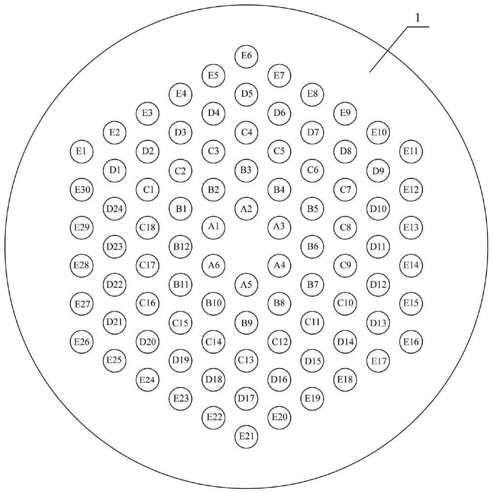
[0038] There are 5 layers of air holes in the cross-sectional structure of the optical fiber. Each layer of air holes in the fiber cross section is arranged in a regular hexagon. The innermost air hole in the center of the fiber is the first layer of air holes, and the outermost air hole in the center of the fiber is The fifth layer of air holes, the number of layers increases layer by layer from the...

specific Embodiment 2

[0064] A method for designing an optical fiber sensing ring of an optical fiber current transformer based on a 650nm wave band, comprising the following steps:

[0065] Step 1. The index-guided chiral photonic crystal fiber is used to replace the original rotating panda-type silicon-based circular polarization fiber. The base material of this optical fiber is polymethyl methacrylate (PMMA) doped with the chiral molecule griseofulvin. The cross-sectional structure of the optical fiber has 5 layers of air holes, such as figure 1 shown. Wherein (1) is composed of the base material of the optical fiber, and the air holes in each layer of the optical fiber cross section are arranged in regular hexagons. Define the layer of air holes closest to the center of the fiber as the first layer of air holes, and the layer of air holes farthest from the center of the fiber as the fifth layer of air holes, and the number of layers increases from the innermost layer to the outermost layer. ...


PUM

PropertyMeasurementUnit
circular birefringenceaaaaaaaaaa
lattice constantaaaaaaaaaa

Abstract

The invention relates to a design method of an optical fiber sensing ring of an optical fiber current transformer based on a 650nm waveband. The invention belongs to the technical field of all-fiber current sensing design. The method comprises the steps of enabling a cross section structure of an optical fiber to be provided with multiple layers of air holes; determining chiral parameters of the optical fiber according to the concentration of griseofulvin in PMMA in a refractive index guide type chiral photonic crystal fiber; determining the value range of the air filling ratio of the opticalfiber, and randomly taking the numerical value meeting the requirement as the final air filling ratio of the optical fiber; and determining the value range of the lattice constant of the optical fiberaccording to the obtained chiral parameters and air filling ratio of the optical fiber, and randomly taking the numerical value meeting the requirement as the final lattice constant of the optical fiber. The ratio difference of an optical fiber current transformer system adopting the scheme of a photonic crystal optical fiber sensing ring is 0.235%, the rationality of the parameter design of thedesigned chiral photonic crystal optical fiber is proved, and the current measurement accuracy of the optical fiber current transformer system is indicated to be improved.

Description

technical field [0001] The invention relates to the technical field of all-fiber current sensing design, and relates to a design method of an optical fiber sensing ring of an optical fiber current transformer based on a 650nm wave band. Background technique [0002] Optical fiber current transformer is a kind of optical fiber sensor based on Faraday rotation effect. Because of its good insulation, high reliability, wide frequency range and good transient characteristics, it is widely used in power transmission industry and electrolytic aluminum industry. These industries have put forward high-precision requirements for the current measurement of optical fiber current transformers. The main factor limiting the accuracy of the system is the imperfection of the optical fiber sensing ring in the system. Polarized light is transmitted in the form of circularly polarized light in an ideal optical fiber sensing ring, but due to the unsatisfactory manufacturing process of the optic...

Claims


Application Information

Patent Timeline
Patent Type & Authority Applications(China)
IPC IPC(8): G02B6/02G02B6/032G01R15/24
CPCG02B6/02328G02B6/032G01R15/246G01R15/247
Inventor 王国臣高鸿泽高伟李社于飞王梓丞苗伟琪王茁
Owner HARBIN INST OF TECH
Why Eureka
Try Eureka