
Power battery recovery and processing equipment and processing method thereof

A power battery, recycling technology, applied in the direction of battery recycling, grain processing, recycling technology, etc., can solve the problems of reducing the service life of the equipment, not playing a buffer role, and corrosion of the main body of the equipment, so as to reduce the loss of electric energy and avoid The effect of incomplete crushing and good circulation crushing

Inactive Publication Date: 2020-11-20
韩邦成
View PDF0 Cites 1 Cited by
  • Summary
  • Abstract
  • Description
  • Claims
  • Application Information

AI Technical Summary

Problems solved by technology

[0004] The purpose of the present invention is to provide a power battery recovery treatment equipment and its treatment method, which mainly solves the defects of the existing power battery recovery treatment equipment. Generally, two motors are used when the power battery is squeezed and crushed, and the equipment is increased. The loss of electric energy does not have the effect of saving energy and reducing consumption, and the pulverized battery is easy to be incompletely pulverized, which makes the subsequent recovery difficult, which reduces the recovery rate of useful metals in the battery, and the pulverized battery falls into the dilute sulfuric acid solution, which may easily cause the dilute sulfuric acid solution to splash As a result, the internal corrosion of the main body of the equipment did not play a good buffer role and reduced the service life of the equipment.

Method used

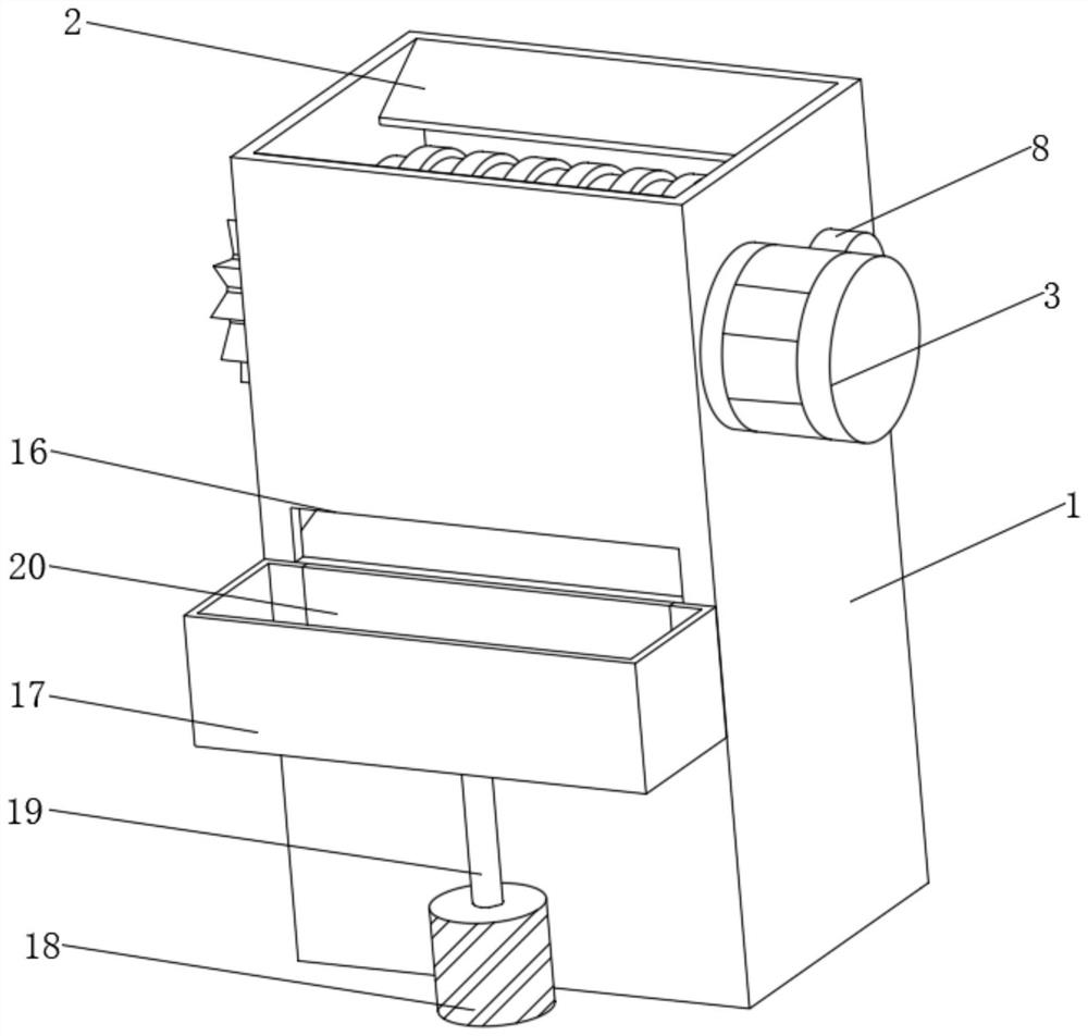
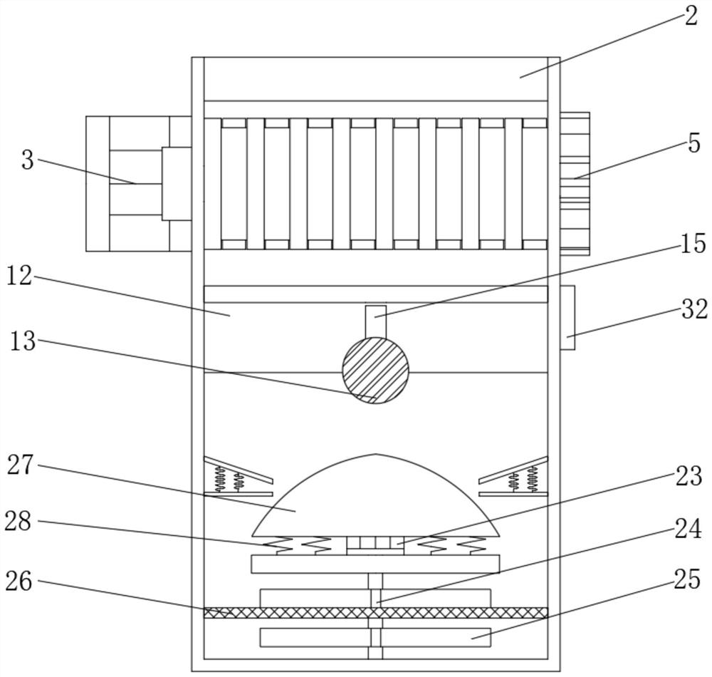
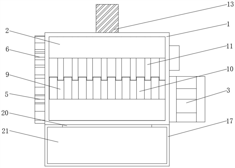

Image

  • Power battery recovery and processing equipment and processing method thereof
  • Power battery recovery and processing equipment and processing method thereof
  • Power battery recovery and processing equipment and processing method thereof

Examples


Embodiment Construction

[0031] The following will clearly and completely describe the technical solutions in the embodiments of the present invention in conjunction with the embodiments of the present invention. Obviously, the described embodiments are only a part of the embodiments of the present invention, rather than all the embodiments. Based on the embodiments of the present invention, all other embodiments obtained by those of ordinary skill in the art without creative work shall fall within the protection scope of the present invention.

[0032] Such as Figure 1-7 As shown, a power battery recycling and processing equipment includes an equipment main body 1. The two inner side walls of the equipment main body 1 close to the top are fixedly connected with a feeding plate 2, and one side of the equipment main body 1 is fixedly installed near the top with a motor 3, No. 1 The output end of the motor 3 is equipped with a driving shaft 4, and the other end of the driving shaft 4 penetrates the main b...


PUM


Abstract

The invention discloses power battery recovery and processing equipment and a processing method of the power battery recovery and processing equipment. The power battery recovery and processing equipment comprises an equipment main body, wherein feeding plates are fixedly connected to positions, close to the tops, of the two inner side walls of the equipment main body. A motor I is fixedly arranged on one side, close to the top, of the equipment main body. A driving shaft is arranged at the output end of the motor I. The other end of the driving shaft penetrates through the equipment main bodyand extends to the outside. The power battery recovery and processing equipment replaces the use of two motors through the cooperation of a driving gear and a driven gear, one motor is reduced duringuse, the loss of electric energy of the recovery equipment is reduced, a certain energy saving and consumption reducing effect is achieved, subsequent recovery difficulties caused by incomplete battery crushing are avoided, the recycling and crushing function is good, the recovery rate of useful metal in a battery is improved, the internal corrosion, caused by the splashing of a dilute sulfuric acid solution caused by falling of a crushed battery, of the equipment main body can be avoided, a good buffering effect is achieved, and the service life of the equipment is prolonged.

Description

Technical field [0001] The invention belongs to the technical field of power battery recovery and treatment, and specifically relates to a power battery recovery and treatment equipment and a treatment method thereof. Background technique [0002] The power battery is the power source that provides the power source for the tool. It mostly refers to the battery that provides power for electric cars, electric trains, electric bicycles, and golf carts. The main risks and hazards of waste batteries are: heavy metals and electrolytes affect soil, water and The environmental pollution of the air, in which the heavy metals contained in the electrode materials cause great environmental damage and pollution to the soil and groundwater, so it is urgent to design a power battery recovery and treatment equipment; [0003] The existing power battery recycling and processing equipment still has certain defects. Generally, two motors are used to crush the power battery, which increases the power ...

Claims


Application Information

Patent Timeline
IPC IPC(8): B02C21/00B02C4/08B02C4/30B02C4/42B02C23/02H01M10/54C22B7/00
CPCB02C4/08B02C4/30B02C4/42B02C21/00B02C23/02B02C2201/06C22B7/007H01M10/54Y02W30/84Y02P10/20
Inventor 韩邦成
Owner 韩邦成
Learn More