Intelligent photoelectric traffic control system and control method thereof

A traffic control and intelligent technology, which is applied in traffic control systems, road vehicle traffic control systems, traffic control supervision, etc., can solve problems such as difficult installation and maintenance, complicated installation and maintenance, and difficult troubleshooting, so as to facilitate the integration of various Ease of function, maintenance and replacement, and the effect of reducing the number of lines

Inactive Publication Date: 2020-11-20
SICHUAN HUAKONG INTELLIGENT TRAFFIC FACILITIES ENG CO LTD
View PDF5 Cites 2 Cited by
  • Summary
  • Abstract
  • Description
  • Claims
  • Application Information

AI Technical Summary

Problems solved by technology

[0005] 2. Difficulties in maintenance and replacement of traffic signal system lines:
[0006] Due to the complex line connections of the traffic signal system, when one line fails, the entire traffic light system will fail, so it is difficult to troubleshoot after a line failure, and the recovery time is long
[0007] 3. There are many network devices in the electronic police system, and installation and maintenance are difficult:
[0008] There are a large number of camera network devices (10+ active devices), and the installation and maintenance are complicated; fiber optic transceivers and intersection switches cannot be managed, and fault location / recovery is difficult; additional red light detectors need to be added to transmit red light information to the camera through 485 lines

Method used


Image

  • Intelligent photoelectric traffic control system and control method thereof

Examples


Embodiment 1

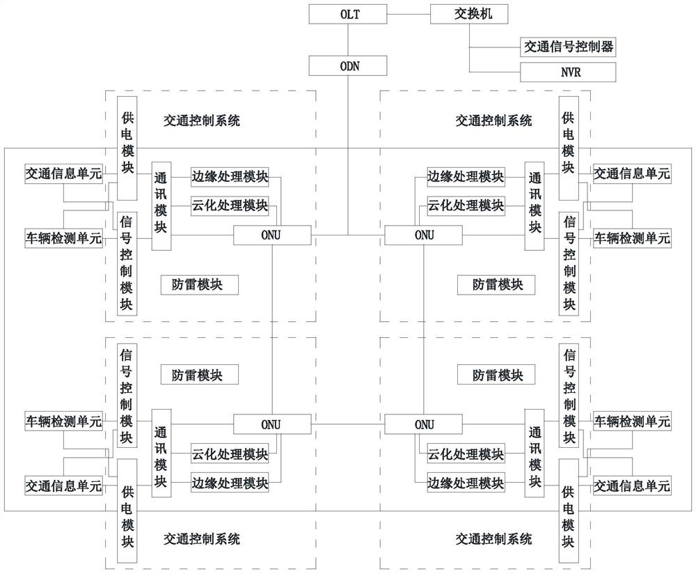
[0045] as attached figure 1 As shown, an intelligent photoelectric traffic control system, including OLT, traffic signal controller, switch, traffic information unit set at each intersection, vehicle detection unit set at each intersection, NVR and traffic control unit set at each intersection control system, each of the traffic control systems includes an ONU, a communication module, a power supply module, a signal control module and a lightning protection module, and the ONU is used to connect with an ONU of an adjacent traffic control system through an optical fiber to form an optical fiber ring network, Establish communication with the communication module and establish communication with the OLT through the ODN;

[0046]The communication module is used to convert the electrical signal obtained from the corresponding power supply module and the signal control module into an optical signal, and output it to the corresponding ONU, and simultaneously convert the optical signa...

Embodiment

[0061] as attached figure 1 As shown, an intelligent photoelectric traffic control system, its system structure is the same as that of Embodiment 1, and on the basis of Embodiment 1, each of the traffic control systems also includes an edge computing module, and the edge computing module is used to obtain The corresponding vehicle data signals collected by the vehicle detection unit converted by the communication module are processed and output to the ONU.

[0062] The setting of the edge computing module can preprocess the vehicle data signal before the vehicle data signal is transmitted to the traffic signal controller, so as to ensure the timeliness of vehicle data signal processing. If the edge computing module is not connected, the vehicle data signal is directly transmitted to the traffic signal controller through the optical fiber ring network for processing.

[0063] Example 3:

[0064] as attached figure 1 As shown, a kind of intelligent photoelectric traffic contr...


PUM


Abstract

The invention discloses an intelligent photoelectric traffic control system. The system comprises an OLT, a traffic signal controller, a switch, traffic information units arranged at all intersections, vehicle detection units arranged at all the intersections, an NVR and traffic control systems arranged at all the intersections, and each traffic control system comprises an ONU, a communication module, a power supply module, a signal control module and a lightning protection module. The invention further discloses a control method of the intelligent photoelectric traffic control system.

Description

technical field [0001] The invention belongs to the field of traffic control, and in particular relates to an intelligent photoelectric traffic control system and a control method thereof. Background technique [0002] A traffic control system generally needs to be installed at a traffic intersection to control traffic and facilitate better passage of vehicles and pedestrians. The current traffic control system has the following problems: [0003] 1. The connection of the traffic signal system is complicated and the construction is difficult: [0004] Generally, there are 4 directions at an intersection, with 3 sets of traffic lights for vehicles and 2 sets of traffic lights for pedestrians in each direction. Each light of the traffic lights needs to be directly driven by a signal controller with 220V live wire, and each set of signal lights needs to be connected to the control machine with wires; such a set of traffic lights Traffic lights need 3 live wires and 1 neutral ...

Claims


Application Information

Patent Timeline
Patent Type & Authority Applications(China)
IPC IPC(8): G08G1/08G08G1/081G08G1/097H04B10/25H04B10/275
CPCG08G1/081G08G1/08G08G1/097H04B10/275
Inventor 陈鹏陈坤华古珮帆
Owner SICHUAN HUAKONG INTELLIGENT TRAFFIC FACILITIES ENG CO LTD
Why Eureka
Try Eureka