Auxiliary heating method for isothermal forging die

An isothermal forging and auxiliary heating technology, applied in the field of forging heating, can solve the problems of poor airtightness, slow temperature return of the mold furnace atmosphere, and easy cracking of the disc wheel rim, so as to reduce thermal stress and cracking tendency, and reduce the number of heating layers. Selecting and solving the effect of wheel rim cracking

Active Publication Date: 2020-11-24
AVIC BEIJING INST OF AERONAUTICAL MATERIALS
View PDF6 Cites 1 Cited by
  • Summary
  • Abstract
  • Description
  • Claims
  • Application Information

AI Technical Summary

Problems solved by technology

However, the existing domestic atmospheric environment near-isothermal forging technology generally adopts the upper and lower split mold heating furnaces, which are covered on the periphery of the isothermal forging mold and simply fixed on the upper and lower mold bases to heat the isothermal forging mold. The efficiency is low. For isothermal forging molds with deep cavity and thick wall thickness, the mold cavity cannot be heated effectively, resulting in the actual temperature of the mold cavity being far lower than the temperature required by the process. Generally, it is only 1000°C to 1020°C. Moreover, during the isothermal forging process, the atmosphere temperature of the mold furnace returns very slowly, and at the same time, the rim of the disc forging is tilted and higher than the forging structure of the spoke plate, which determines that the alloy rim is always subject to circumferential tensile stress when filling the shape, resulting in disc forging. The rim part is easy to crack, which affects the appearance integrity and internal structure of the disc forging, and serious cracks cause the disc to be scrapped directly

Method used


Image

  • Auxiliary heating method for isothermal forging die
  • Auxiliary heating method for isothermal forging die

Examples


Embodiment Construction

[0024] The technical scheme of the present invention will be described in further detail below in conjunction with accompanying drawing and embodiment:

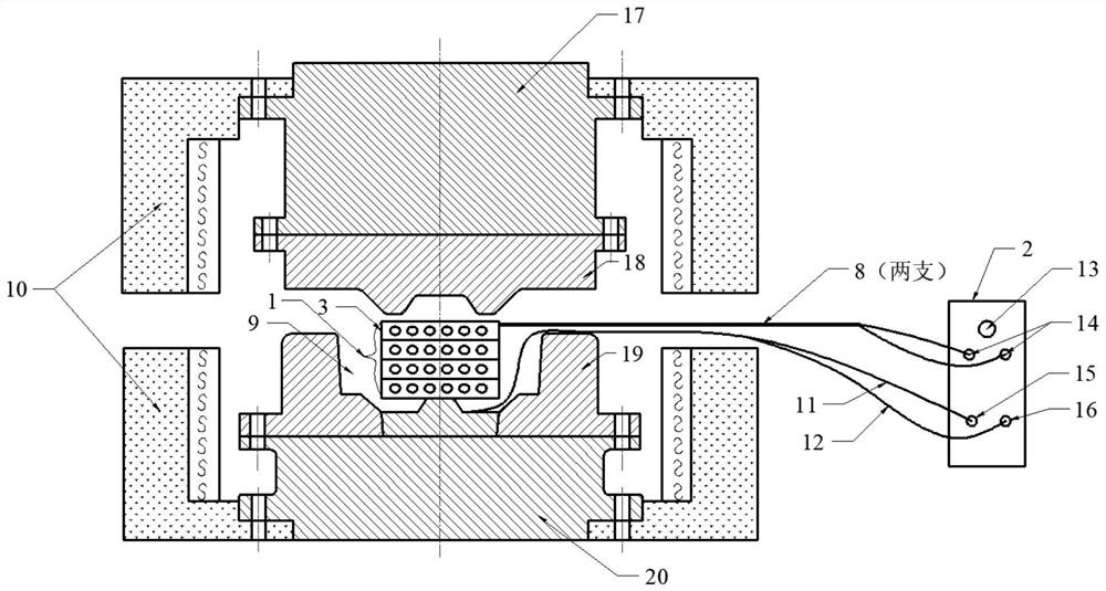
[0025] See attached figure 1 , 2 As shown, in this embodiment, the size of the isothermal forging die is: cavity Φ640×100 mm, outer profile Φ1000×1200 mm, shape: single hole, circular, material: N3 superalloy.

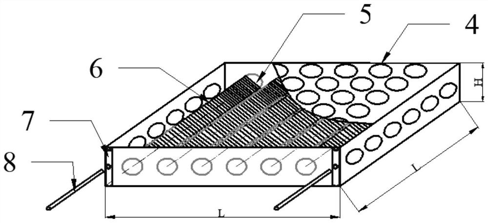
[0026] This kind of auxiliary heating device for isothermal forging molds includes a heater 1 and a portable control cabinet 2. The heater 1 is composed of three layers of heating elements 3 superimposed. The two ends of the resistance wire 6 are drawn out of the mold furnace 10 and connected to the output power interface 14 on the portable control cabinet 2. The temperature measuring terminals of the temperature control thermocouple 11 and the monitoring thermocouple 12 are placed in the middle of the surface of the mold cavity 9, Located under the heater 1, the thermocouple signal terminal is connected to the temp...


PUM

PropertyMeasurementUnit
Diameteraaaaaaaaaa
The inside diameter ofaaaaaaaaaa
Wall thicknessaaaaaaaaaa

Abstract

The invention discloses an auxiliary heating method for an isothermal forging die. According to the auxiliary heating method, in a conventional isothermal forging die heating furnace, a die is heatedfrom the external part of the die, and an auxiliary heating device is adopted to heat the die from the cavity of the die, so that the die temperature gradient is lowered when the die is heated from the external part, the thermal stress and tearing tendency of the die are reduced, and the actual temperature of the die cavity is ensured to meet the forging technological requirements; and in addition, due to portability and selective flexibility of the heating layer number (power), additional heating can be carried out on the die cavity to compensate heat loss and heat reduction caused by repeated opening and closing of a die furnace. The auxiliary heating device adopted by the method is flexible and portable, and simple and convenient in mounting and using, ensures the temperature of the diecavity, solves the problems that a forge piece rim cracks and is abnormal in texture due to excessively low die cavity temperature and increases the yield and the economic benefit.

Description

technical field [0001] The invention relates to an auxiliary heating method for an isothermal forging die, which belongs to the technical field of forging heating. Background technique [0002] A powder superalloy disc forging for a certain type of aero-engine is a disc forging whose rim is tilted to a certain height and is higher than the spoke plate. It is prepared by AA atomization powder production + hot isostatic pressing (HIP) + isothermal forging (HIF) Routing. Because of the high degree of alloying of the powder superalloy used, the hot forming performance is extremely sensitive to temperature, and the processing window is narrow, the requirements for the execution of the isothermal forging process are very strict. [0003] The forging forming temperature of the forging is 1050-1100°C, and the atmosphere temperature of the mold heating furnace is required to be 1050-1070°C. However, the existing domestic atmospheric environment near-isothermal forging technology ge...

Claims


Application Information

Patent Timeline
IPC IPC(8): B21J13/02B21K29/00
CPCB21J13/02B21K29/00
Inventor 王超渊周晓明宋晓俊冯业飞邹金文
Owner AVIC BEIJING INST OF AERONAUTICAL MATERIALS
Why Eureka
Try Eureka