
High-precision fiber bragg grating signal demodulation system and method

A fiber grating and signal demodulation technology, which is applied in the direction of using optical devices to transmit sensing components, converting sensor outputs, measuring devices, etc., can solve the problem of inability to accurately measure the physical quantities of fiber grating sensors, and achieve high demodulation accuracy and detection efficiency. The effect of high and low dark counts

Pending Publication Date: 2020-11-24
UNIV OF ELECTRONIC SCI & TECH OF CHINA
View PDF4 Cites 1 Cited by
  • Summary
  • Abstract
  • Description
  • Claims
  • Application Information

AI Technical Summary

Problems solved by technology

[0003] Based on the above problems, the present invention provides a high-precision fiber grating signal demodulation system and its method, which solves the problem that the physical quantity of the fiber grating sensor cannot be accurately measured in the existing detection methods

Method used


Image

  • High-precision fiber bragg grating signal demodulation system and method
  • High-precision fiber bragg grating signal demodulation system and method
  • High-precision fiber bragg grating signal demodulation system and method

Examples


Embodiment Construction

[0038] The present invention will be further described below in conjunction with the accompanying drawings. Embodiments of the present invention include, but are not limited to, the following examples.

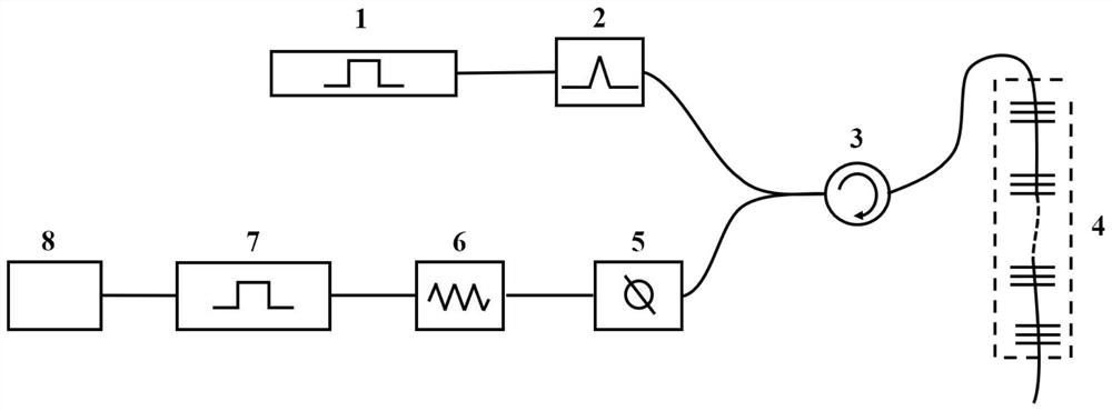
[0039] Such as figure 1 As shown, a high-precision fiber grating signal demodulation system includes a pulse driving source 1, a laser 2, a circulator 3, a fiber grating sensor 4, an adjustable attenuator 5, a single photon detector 6, and a time-to-digital converter 7 and information processor 8, wherein:

[0040] The pulse driving source 1 is used to make the pulse width of the laser 2 output pulsed light in nanosecond or picosecond level;

[0041] The laser 2 is used to generate two narrow linewidth output lasers with similar wavelengths. The laser 2 can be a distributed feedback laser and / or a dye laser and / or a tunable fiber laser. It should be noted that the pulsed light emitted by the laser 2 The wavelength of is located in the reflection spectral range of the fiber ...


PUM


Abstract

The invention relates to the field of fiber bragg grating signal demodulation, and in particular, relates to a high-precision fiber bragg grating signal demodulation system which comprises a pulse driving source, a laser, a circulator, a fiber bragg grating sensor, an adjustable attenuator, a single-photon detector, a time-to-digital converter and an information processor. The fiber bragg gratingsignal demodulation method comprises the following steps that: step 1, a laser device emits lasers with different wavelengths, and the lasers reach the fiber bragg grating sensor through the circulator and are reflected to the single-photon detector; step 2, the time-to-digital converter measures a single-photon counting value reaching the single-photon detector; step 3, the information processorobtains a measurement signal according to the single photon counting value measured by the time-to-digital converter, and the measurement signal change amount of the two reflected pulse light reachingthe single photon detector can be obtained according to the measurement signal; and step 4, the drift amount of the reflection center wavelength of the fiber bragg grating is demodulated according tothe change amount of the measurement signal. The problem that in an existing detection mode, the physical quantity of the fiber grating sensor cannot be accurately measured is solved.

Description

technical field [0001] The invention relates to the field of fiber grating signal demodulation, in particular to a high-precision fiber grating signal demodulation system and a method thereof. Background technique [0002] Fiber Bragg Grating Sensing Technology Fiber Bragg grating sensor is one of the most widely used fiber optic wavelength modulation sensors. It has the advantages of electromagnetic interference capability, good electrical insulation performance, corrosion resistance, high sensitivity, and large transmission capacity. It has a wide range of applications in structural safety measurement. application. The traditional FBG wavelength demodulation method is to demodulate the FBG wavelength by means of frequency sweep, which requires the use of additional optical devices, such as FP interferometers, but is expensive and not portable. At present, the time-domain demodulation of dual-wavelength fiber gratings has been realized by using tunable lasers, without addi...

Claims


Application Information

Patent Timeline
IPC IPC(8): G01D5/353G01D5/38
CPCG01D5/35354G01D5/38
Inventor 欧中华范潇东张婧蕾周强刘永
Owner UNIV OF ELECTRONIC SCI & TECH OF CHINA
Learn More