Anchor drilling jig provided with rod-protection mechanical hand and used for coal mine

A technology of bolt drilling rig and manipulator, which is applied to the installation of bolts, drill pipes, drill pipes, etc., can solve the problems of safety threats to operators, unbalanced driving and anchoring protection, and increased resistance of anchor drilling, so as to reduce the labor intensity of workers. , Improve the efficiency of anchoring protection and reduce the resistance of the protection rod

Active Publication Date: 2020-11-27
TAIYUAN INST OF CHINA COAL TECH & ENG GROUP +1
View PDF4 Cites 4 Cited by
  • Summary
  • Abstract
  • Description
  • Claims
  • Application Information

AI Technical Summary

Problems solved by technology

At the same time, in the current roadway anchor protection operation, there is a serious problem of unbalanced tunneling and anchor protection. The anchor protection operation time is three times that of the excavation operation time, resulting in adverse consequences such as excavation and other anchor protection, which seriously restricts the rapid excavation of coal mines. Therefore, the realization of high-efficiency and rapid anchor protection is imminent. The most direct way is to increase the anchor drilling speed. Drilling resistance is greatly increased, and even broken rods or flying rods may occur, which will have a great impact on the anchor drilling speed and at the same time pose a great threat to the safety of operators. To solve this outstanding problem, this patent has developed a protective rod. Coal mine rock bolter with manipulator

Method used


Image

  • Anchor drilling jig provided with rod-protection mechanical hand and used for coal mine
  • Anchor drilling jig provided with rod-protection mechanical hand and used for coal mine
  • Anchor drilling jig provided with rod-protection mechanical hand and used for coal mine

Examples


Embodiment Construction

[0050] The specific embodiment of the present invention will be further described in conjunction with accompanying drawing:

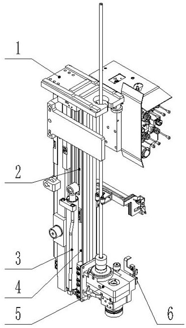
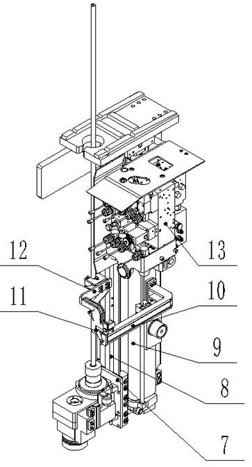
[0051] The present invention is a coal mine rock bolter with a guard rod manipulator specially developed to realize the function of the guard rod in the drilling process of the drill pipe, which effectively solves the working condition of the coal mine rock bolter in the anchor protection process, especially the need to connect rods Under the circumstances, the rod throwing problem caused by the excessive length of the drill pipe has greatly improved the reliability of the high-speed anchor drill of the drilling rig. It can be matched with the relevant rock bolter equipped with the airborne rock bolter.

[0052] Such as figure 1 , 2 As shown, the present invention includes temporary support, frame assembly, short-feed oil cylinder, carriage assembly, drilling box, ejector rod hook-back device, guide connecting plate, chain transmission device, long-fe...


PUM


Abstract

The invention belongs to anchor rod support equipment, and particularly relates to an anchor drilling jig provided with a rod-protection mechanical hand and used for a coal mine. A sliding frame assembly is mounted on a frame assembly. A long feeding oil cylinder is mounted at the bottom of the frame assembly. A cylinder barrel lug base of the long feeding oil cylinder is connected with a long feeding oil cylinder fixing lug base of the frame assembly. A cylinder rod lug base of the long feeding oil cylinder is connected with a top plate of the sliding frame assembly. A guide connecting platewhich can slide relatively is mounted on the sliding frame assembly and is fixedly connected with a drilling box. A top rod back-hooking device which can turn a mechanical paw is fixed to one side ofthe drilling box. A mechanical hand protection arm and the mechanical paw are connected to the frame assembly. One end of a chain transmission device is connected with the guide connecting plate, andthe other end of the chain transmission device is connected with the sliding frame assembly. The chain transmission device is wound on a short feeding oil cylinder through a sliding wheel assembly, and the guide connecting plate is improved by multiple times through a sliding wheel device composed of a short feeding oil cylinder stretching chain drive device and the guide connecting plate.

Description

technical field [0001] The invention belongs to rock bolt support equipment, in particular to a rock bolt drill for coal mines with a manipulator of a protective rod. Background technique [0002] The current support method in the roadway excavation process is mainly bolt support. During the anchoring and protection process of the rock bolter, sometimes the phenomenon of rod throwing or even broken rods may occur. Therefore, when the rock bolter is anchoring and protecting, workers often need to protect the drill pipe with their hands and go up to the top position, which is very dangerous and greatly affects Drilling speed. How to realize the automatic protection rod through the protection rod device that comes with the rock bolt rig is an urgent problem to be solved to solve the bolt throwing of the anchor drill and ensure the safety of workers' anchor protection work. At the same time, in the current roadway anchor protection operation, there is a serious problem of unba...

Claims


Application Information

Patent Timeline
Patent Type & Authority Applications(China)
IPC IPC(8): E21D20/00E21B7/02E21B19/14
CPCE21D20/003E21B7/024E21B19/14
Inventor 王富强丁永成李明科王威杜玉祥仇卫建左岗永张维果兰辉敏朱大鹏孟雯杰陈明健张云波徐双用侯相华
Owner TAIYUAN INST OF CHINA COAL TECH & ENG GROUP
Why Eureka
Try Eureka