
Ship-borne impact type swing drive wave generator

An impact type and generator technology, applied in the direction of engines, ocean energy power generation, engine components, etc., can solve the problems of harsh design and working conditions, high installation and maintenance costs, low power generation density, etc., and achieve energy conversion efficiency and volume High power density, simple structure and reliable operation

Pending Publication Date: 2020-11-27
NANJING VOCATIONAL UNIV OF IND TECH
View PDF0 Cites 6 Cited by
  • Summary
  • Abstract
  • Description
  • Claims
  • Application Information

AI Technical Summary

Problems solved by technology

Permanent floating devices such as marine communication towers, navigation lights, fish ponds and cage aerators also need electricity. Due to factors such as limited volume, cost and use efficiency, and inconvenient maintenance, it is usually inconvenient to configure fuel-powered devices To generate electricity to solve power supply problems, generally use batteries for power supply and replace them regularly
[0003] In order to reduce power consumption and save energy, some ships and floating devices use wind power or solar cells as backup or permanent power sources for mooring. Due to the disadvantages of high installation and maintenance costs, high installation location and poor wind resistance, it is difficult to popularize
In fact, the endless waves in rivers, lakes and seas contain enormous energy and are far higher than the energy density of wind and sunlight. There are also some beach power stations that use waves to generate electricity, but their mechanisms are relatively complicated, and it is difficult to achieve volume and The weight is miniaturized, the design working conditions are harsh, and the cost is high, so it is difficult to transplant and apply to small ships and permanent floating devices

Method used


Image

  • Ship-borne impact type swing drive wave generator
  • Ship-borne impact type swing drive wave generator
  • Ship-borne impact type swing drive wave generator

Examples


Embodiment Construction

[0026] In order to make the technical means, creative features, goals and effects achieved by the present invention easy to understand, the present invention will be further described below in conjunction with specific embodiments.

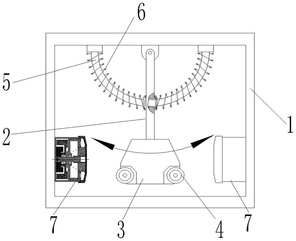
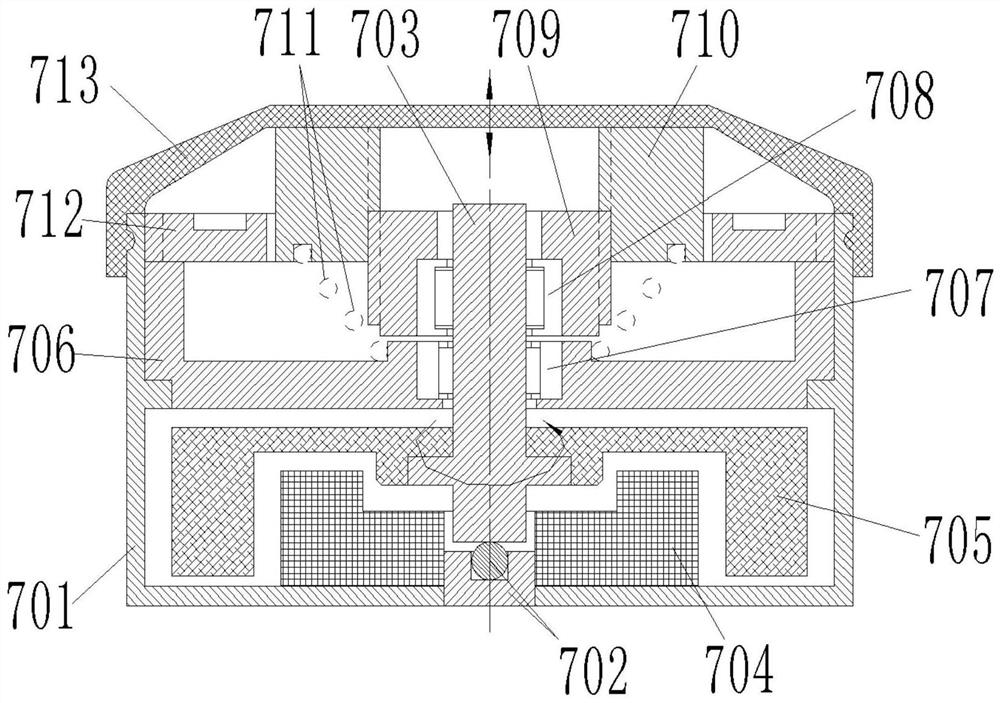
[0027] refer to Figure 1 to Figure 3 , this embodiment discloses a ship-borne impact-type swing-driven wave generator, including a base 1, a swing rod 2, a pendulum 3, an impact roller 4, an arc-shaped guide rod 5, a damping spring 6 and an impact generator 7 ;

[0028] The pendulum 3 is rotatably suspended above the center of the machine base 1 through the pendulum 2, the arc-shaped guide rod 5 freely runs through the hole in the middle section of the pendulum 2, and the damping spring is sleeved on the pendulum 2 in two sections, left and right, and both ends Supported on the machine base 1 and the pendulum rod 2, two impact rollers are respectively arranged on the two sides of the lower part of the pendulum 3;

[0029] The impact generator 7...


PUM


Abstract

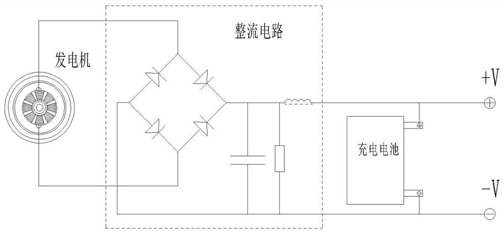
The invention discloses a ship-borne impact type swing driven wave generator, and relates to the field of new energy equipment. The wave generator comprises a base, a pendulum rod, a pendulum, impactrollers, an arc guide rod, damping springs and impact generators. An inertial vibrator comprising the damping springs and a mass block composed of the pendulum rod, the pendulum and the impact rollersis utilized for absorbing wave energy which pushes a hull to swing, impact acts on unidirectional bearing mechanisms and is converted into unidirectional rotation of a generator rotor, and mechanicalenergy is temporarily stored in the form of rotational inertial energy; meanwhile, pulsating induced potential is produced by coupling of stator coils of the generators to the magnetic fields of rotors; and finally, a rectifier circuit and an energy storage battery are utilized for converting pulsating potential into stable voltage and supply power to ship-borne electrical load equipment. The wave generator has the advantages of simple structure, high energy conversion efficiency and volume power density, reliable operation, low cost and the like.

Description

technical field [0001] The invention belongs to the field of new energy equipment, and in particular relates to a ship-mounted impact-type swing-driven wave generator. Background technique [0002] Small ships such as small yachts, fishing boats, and traffic boats need power to provide lighting, communication, and some domestic and low-power production electricity even when they are anchored. The electricity is stored as a power supply. Permanent floating devices such as marine communication towers, navigation lights, fish ponds and cage aerators also need electricity. Due to factors such as limited volume, cost and use efficiency, and inconvenient maintenance, it is usually inconvenient to configure fuel-powered devices To generate electricity to solve the power supply problem, batteries are generally used for power supply and replaced regularly. [0003] In order to reduce power consumption and save energy, some ships and floating devices use wind power or solar cells as...

Claims


Application Information

Patent Timeline
Patent Type & Authority Applications(China)
IPC IPC(8): F03B13/14F03G3/06
CPCF03B13/14F03G3/06Y02E10/30
Inventor 白顺科
Owner NANJING VOCATIONAL UNIV OF IND TECH
Learn More