High-frequency ultrasonic pulse generator and optimization method

A pulse generator, ultrasonic pulse technology, applied in pulse generation, pulse technology, electrical components, etc., can solve the problems of limited pulse amplitude and pulse power of a single avalanche tube

Active Publication Date: 2020-11-27
INST OF ACOUSTICS CHINESE ACAD OF SCI
View PDF3 Cites 0 Cited by
  • Summary
  • Abstract
  • Description
  • Claims
  • Application Information

AI Technical Summary

Problems solved by technology

Considering that when the BJT works in the avalanche region, the switching speed of the BJT is faster due to the carrier multiplication effect. In 1993, Chen Gelin used a single avalanche tube 3DB2I to generate a unipolar high-voltage pulse with a pulse width of 5-10ns to excite high-frequency ultrasonic transducers. device, but the pulse amplitude and pulse power of a single avalanche tube are limited

Method used


Image

  • High-frequency ultrasonic pulse generator and optimization method
  • High-frequency ultrasonic pulse generator and optimization method
  • High-frequency ultrasonic pulse generator and optimization method

Examples


Embodiment 1

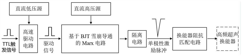
[0056] build as figure 1 The high-frequency ultrasonic pulse generator shown includes a DC low-voltage source, a DC high-voltage source, a high-speed drive circuit, a Marx circuit, an isolation circuit and a transducer impedance matching circuit.

[0057] The DC low-voltage source provides the working voltage V to the high-speed drive circuit DD .

[0058] The DC high voltage source provides the Marx circuit with avalanche breakdown voltage BV close to the BJT in the Marx circuit CES The supply voltage V CC .

[0059] The high-speed driving circuit is composed of 4 inverting Schmitt triggers in series, which receive the TTL trigger signal, convert the TTL trigger signal into a driving signal and send it to the Marx circuit. Such as Figure 6 As shown, the high-speed drive circuit uses the 74AHCT14D chip, which is a high-speed silicon gate CMOS device, and can provide up to six inversion buffers with Schmitt trigger functions.

[0060] The Marx circuit consists of a 5-lev...

Embodiment 2

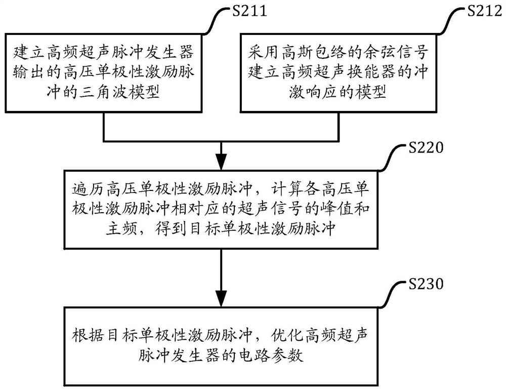
[0066] use as figure 2 The shown method optimizes the high-frequency ultrasonic pulse generator of the first embodiment. It is determined that the load connected in parallel with the parallel capacitor C is a 200MHz high-frequency ultrasonic transducer. After testing, the center frequency f of the high-frequency ultrasonic transducer is 0 It is 177.5MHz, and the relative bandwidth B is 0.726.

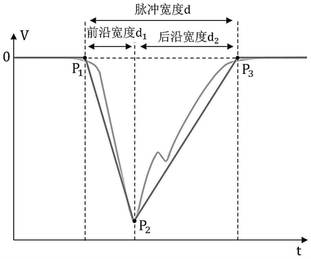
[0067] According to the center frequency f of the high frequency ultrasonic transducer 0 , determine the pulse width d=0.766 / f of the target unipolar excitation pulse 0 = 4.315 ns. and when d 1 = d 2 =2.158ns, the peak value of the ultrasonic signal is the largest. At this time, the peak frequency of the ultrasonic signal f m close to the transducer center frequency f 0 (i.e. f 0 -f m 0 ), the ultrasonic signal has the optimal peak value and peak frequency.

[0068] According to formula 3 get: d 1 =1.24×2 / (2πf T ) = 2.158 ns. From this we get the BJT characteristic freque...


PUM


Abstract

The invention relates to a high-frequency ultrasonic pulse generator and an optimization method. The pulse generator comprises: a high-speed drive circuit which receives a TTL trigger signal and converts the TTL trigger signal into a drive signal; a Marx circuit based on BJT avalanche conduction which receives the driving signal, drives BJT avalanche conduction according to the driving signal andthe power supply voltage, and outputs a high-voltage unipolar excitation pulse; an isolation circuit which receives the high-voltage unipolar excitation pulse and isolates the ultrasonic echo signal;and a transducer impedance matching circuit which performs impedance matching on the high-frequency ultrasonic transducer. The optimization method comprises the following steps: establishing a triangular wave model of a high-voltage unipolar excitation pulse; establishing an impulse response model of the high-frequency ultrasonic transducer; if the amplitude is constant, traversing the high-voltage unipolar excitation pulses, and calculating peak values and peak value frequencies of the ultrasonic signals corresponding to the high-voltage unipolar excitation pulses to obtain target unipolar excitation pulses; and optimizing circuit parameters of the high-frequency ultrasonic pulse generator according to the target unipolar excitation pulse.

Description

technical field [0001] The invention relates to the field of ultrasonic detection, in particular to a high-frequency ultrasonic pulse generator and an optimization method for the high-frequency ultrasonic pulse generator. Background technique [0002] In 1924, E.Marx proposed a Marx generator that generates high-voltage pulses through a low-voltage DC power supply based on the principle of capacitors being charged in parallel and discharged in series. Early Marx generators were mainly used in high-energy physics experiments. In the 1950s, avalanche tubes began to enter the field of nanosecond pulse technology. In the 1960s, Bell, Prince, Hansen and others successively carried out research on the Marx circuit of avalanche tubes. Marx generators began to be widely used in laser systems and ultra-wideband radars. and nuclear physics. [0003] At present, there are two main methods of conventional ultrasonic excitation: (1) A high-speed switching circuit composed of a bipolar j...

Claims


Application Information

Patent Timeline
Patent Type & Authority Applications(China)
IPC IPC(8): H03K4/06
CPCH03K4/06
Inventor 王坤冷涛张逸君廉国选
Owner INST OF ACOUSTICS CHINESE ACAD OF SCI
Why Eureka
Try Eureka