A Coordinated Control Method of Receiving-end Cascaded Hybrid DC Based on Dynamic Limiting

A hybrid DC and coordinated control technology, which is applied in AC network circuits, power transmission AC networks, circuit devices, etc., can solve the problems of unmixed DC system control characteristics research, poor versatility, and unanalyzed system UI characteristic curves, etc., to avoid Organize the effect of inverter mode change, enhanced voltage stability, and simple and easy control strategy

Active Publication Date: 2022-01-21
JIANGSU ELECTRIC POWER RES INST +3
View PDF0 Cites 0 Cited by
  • Summary
  • Abstract
  • Description
  • Claims
  • Application Information

AI Technical Summary

Problems solved by technology

[0008] Disadvantages of measure 1: only studied the steady-state and fault characteristics of the hybrid cascaded DC transmission system under different terminal wiring and control modes, did not analyze the UI characteristic curve of the system, and did not propose a coordinated control strategy for the fault response of the system
[0009] Measure 2 Disadvantage: A recovery control strategy for the hybrid cascaded DC transmission system during the DC fault period and after the fault is cleared is proposed, which alleviates the overcurrent phenomenon during the fault period, but this control strategy is only for DC faults and has poor versatility
[0010] Measure 3 Disadvantages: The device configuration method of the bypass switch series resistor and diode for current suppression is proposed, but the control characteristics of the hybrid DC system are not studied in depth

Method used


Image

  • A Coordinated Control Method of Receiving-end Cascaded Hybrid DC Based on Dynamic Limiting
  • A Coordinated Control Method of Receiving-end Cascaded Hybrid DC Based on Dynamic Limiting
  • A Coordinated Control Method of Receiving-end Cascaded Hybrid DC Based on Dynamic Limiting

Examples


Embodiment Construction

[0047] The present invention will be further described in detail below in conjunction with the accompanying drawings and specific embodiments.

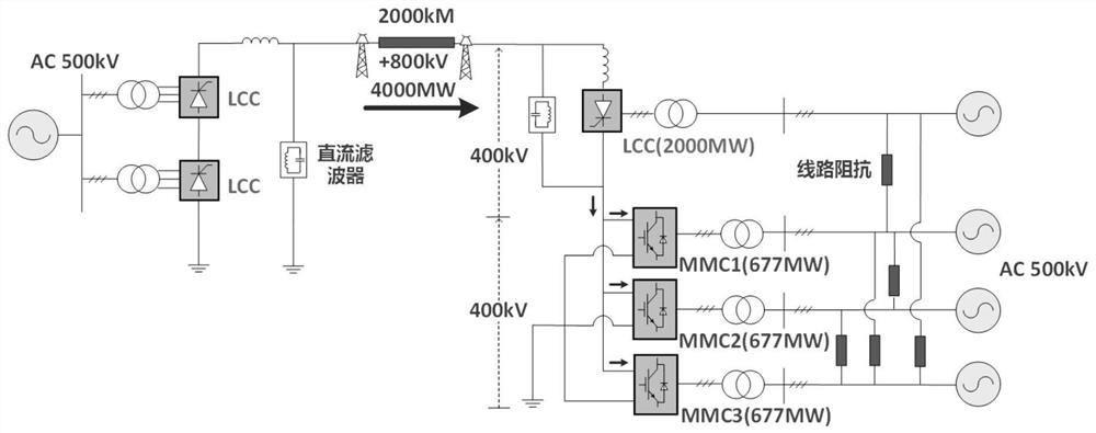
[0048] 1. Receiver cascade hybrid DC control characteristics (master-slave control)

[0049] When the receiving MMC adopts the master-slave control mode, this control mode mainly determines the power distribution among the MMCs in terms of current characteristics, and its changes to the overall UI characteristic curve of the hybrid DC are mainly concentrated in the voltage characteristic curve.

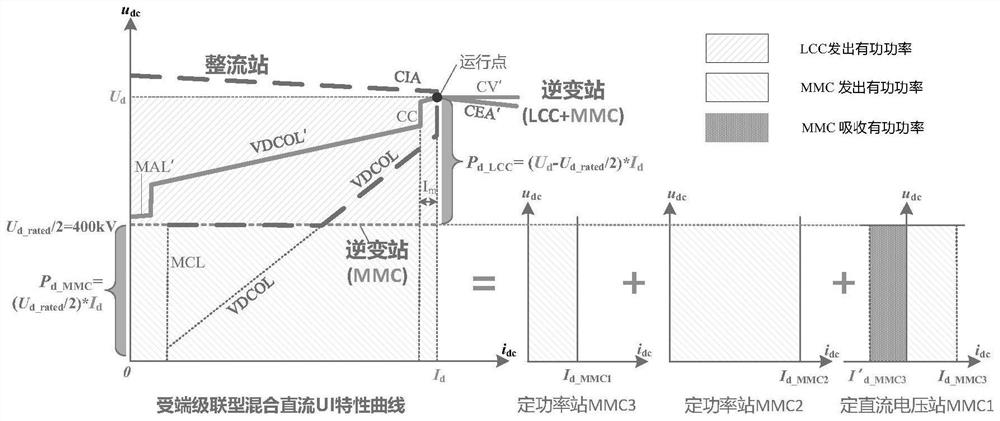
[0050] Due to the characteristics of the MMC constant DC voltage station, and there is no additional control such as low-voltage current limiting, the UI characteristic curve of the MMC in the mixed DC under master-slave control is shown in formula (1).

[0051]

[0052] Among them, u dc_MMC is the DC voltage controlled by the MMC, which is the hybrid DC rated DC voltage U d_rated half of.

[0053] In terms of the characteristic curve o...


PUM


Abstract

The invention discloses a receiving-end cascaded hybrid direct current coordinated control method based on dynamic limiting, comprising the following steps: under the master-slave control mode adopted by the MMC, the overall UI characteristic curve of the receiving-end cascaded hybrid direct current transmission system is clarified ; The dynamic limiting link is set in the fixed power flexible converter station of cascaded hybrid direct current transmission at the receiving end. The method of the invention can release the reactive power support potential of the flexible DC to the AC system to enhance the voltage stability of the AC system when the receiving end system fails, and can automatically limit the active power output of the constant power station to avoid the flexibility of the constant DC voltage. The finishing and inverter mode of the converter station is changed, which improves the system stability in terms of active frequency and reactive voltage.

Description

technical field [0001] The invention relates to the field of hybrid direct current transmission, in particular to a receiving-end cascaded hybrid direct current coordinated control method based on dynamic limiting. Background technique [0002] Hybrid DC transmission has become an important development direction of DC transmission technology in recent years because it combines the advantages of conventional DC (LCC-HVDC) and flexible DC (VSC-HVDC). Receiver cascaded hybrid DC power transmission (such as figure 1 )’s rectifier station consists of two sets of 12-pulse grid commutated converters (LCC) connected in series, and the inverter station consists of a set of 12-pulse LCCs and voltage source converters (VSC) connected in series in parallel, and the low-end VSC is extended Multiple VSCs are connected in parallel and placed on different regional power grids. While increasing the transmission power of the hybrid DC system, the multi-drop structure is also conducive to the...

Claims


Application Information

Patent Timeline
Patent Type & Authority Patents(China)
IPC IPC(8): H02J3/36H02J3/48H02J3/50
CPCH02J3/36H02J3/48H02J3/50H02J2203/20Y02E60/60
Inventor 赵静波朱鑫要解兵王大江曾蕊李保宏
Owner JIANGSU ELECTRIC POWER RES INST
Why Eureka
Try Eureka