Recycling method for machining cutting fluid

A recycling method and cutting fluid technology, applied in metal processing equipment, chemical instruments and methods, metal processing machinery parts, etc., can solve the problems of affecting large particles of impurities, low impurity removal efficiency, internal impurity removal, etc., to ensure the quality of filtration Effect

Inactive Publication Date: 2020-12-04
许翠英
View PDF0 Cites 9 Cited by
  • Summary
  • Abstract
  • Description
  • Claims
  • Application Information

AI Technical Summary

Problems solved by technology

[0003] The existing recovery device needs to filter the chips, small iron pieces and sand particles in the cutting fluid before they can be reused. However, when the existing recovery device is used, the used cutting fluid is generally poured into the device. In the recovery device, iron filings, small iron nuggets and other impurities in the cutting fluid are removed by sedimentation and insertion of electromagnetic rods. However, large particles of impurities must be removed by sedimentation. This method of removing impurities is not only inefficient, but also For the method of inserting electromagnetic rods into it to absorb small iron filings and other impurities, due to the size limitation of the electromagnetic rods, for a recovery device with a large amount of used cutting fluid, the amount of impurities that can be adsorbed on each electromagnetic rod If the mass is too small and the adsorption range is very limited, if the internal liquid flow is not increased by agitation, the internal impurities cannot be removed more completely, but if agitation will affect the large particles of impurities precipitated at the bottom, It is remixed in the cutting fluid, so multiple equipment processes are needed to complete the recovery effect of the cutting fluid, so the existing recovery devices are not very ideal in terms of recovery efficiency and effect

Method used


Image

  • Recycling method for machining cutting fluid
  • Recycling method for machining cutting fluid
  • Recycling method for machining cutting fluid

Examples


Embodiment Construction

[0030] The embodiments of the present invention will be described in detail below with reference to the accompanying drawings, but the present invention can be implemented in many different ways defined and covered by the claims.

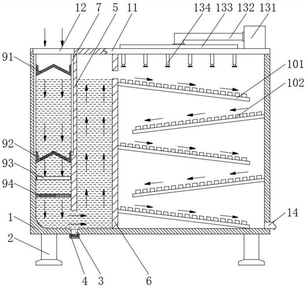
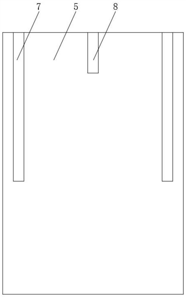
[0031] Such as Figure 1 to Figure 6 As shown, a machining cutting fluid recovery method, the machining cutting fluid recovery method adopts the following cutting fluid recovery device, the device includes a box 1 and a support leg 2, and the support leg 2 is fixedly installed on the lower surface of the box body 1, The bottom end of the left side of the box body 1 is fixedly installed with a bottom liquid outlet 3, and one end of the bottom liquid outlet 3 is threaded with a sealing cover 4, and the left side of the box body 1 is fixedly installed between the front and the back with a first The partition 5 and the second partition 6, the second partition 6 is located on the right side of the first partition 5, and the left front and back sides of t...


PUM


Abstract

The invention relates to a recycling method for machining cutting fluid. The recycling method for the machining cutting fluid adopts the following cutting fluid recycling device; the cutting fluid recycling device comprises a box body and supporting legs; the supporting legs are fixedly installed at the lower surface of the box body; a bottom liquid outlet is fixedly installed at the bottom end ofthe left side of the box body; a U-shaped communicating vessel structure is arranged at one end of the left side of the device, so that large-particle impurities in the device are filtered out through a first filter plate and a second filter plate which are arranged in the device; afterwards, through a first turbulent flow plate and a second turbulent flow plate, the preliminarily filtered liquidreaches a laminar-flow-like state, and the flow resistance of the cutting fluid in the liquid is increased, so that the flow speed of the cutting fluid at the bottom of the U-shaped communicating vessel structure is reduced, and then impurities can be settled again in a slow flowing process of the waste cutting fluid; and thus, relatively large impurities in the cutting fluid are removed to guarantee the subsequent filtration quality of the cutting fluid.

Description

technical field [0001] The invention relates to the technical field of recycling cutting fluid, in particular to a method for recycling cutting fluid in machining. Background technique [0002] Cutting fluid is an industrial liquid used for cooling and lubricating cutting tools and workpieces during the grinding process of metal chips. down, to prevent contamination of the machine tool, workpiece, and cutting tool, to ensure that the cutting edge of the cutting tool or grinding wheel remains sharp without affecting the cutting effect, and the used cutting fluid will be recycled and reused through the recycling device, but the existing recycling device There are some problems: [0003] The existing recovery device needs to filter the chips, small iron pieces and sand particles in the cutting fluid before they can be reused. However, when the existing recovery device is used, the used cutting fluid is generally poured into the device. In the recovery device, iron filings, sm...

Claims


Application Information

Patent Timeline
Patent Type & Authority Applications(China)
IPC IPC(8): B23Q11/00B24B57/00B23Q11/10B03C1/02
CPCB03C1/02B23Q11/00B23Q11/10B23Q11/1069B24B57/00
Inventor 许翠英金严李超
Owner 许翠英
Why Eureka
Try Eureka