Electrode sheet slotting method and device
A slotting method and pole piece technology, which is applied in electrode forming, electrode manufacturing, electrochemical generator, etc., can solve the problems of large tolerance and high cost, speed up the production cycle, improve the processing accuracy, and avoid damage to the current collector layer. Effect
- Summary
- Abstract
- Description
- Claims
- Application Information
AI Technical Summary
Problems solved by technology
Method used
Image

Examples
no. 1 example
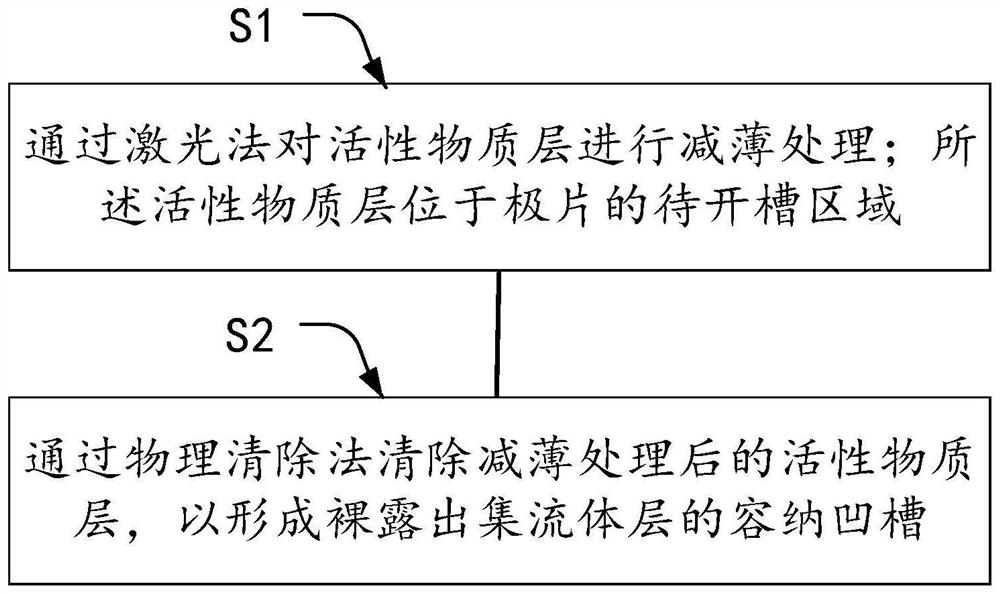
[0026] refer to figure 1 , the pole piece slotting method provided in the first embodiment of the present application includes:
[0027] Step S1: Thinning the active material layer by laser method; the active material layer is located in the area of the pole piece to be grooved. After thinning the active material layer, the range of the thickness H of the active material layer is: 30 microns≥H≥1 micron.
[0028] Step S2: removing the thinned active material layer by a physical removal method to form a receiving groove exposing the current collector layer. The accommodating grooves processed above can be used to accommodate tabs, and the tabs are welded and fixed to the exposed current collector layer.
[0029] In the present application, the laser method is first used to thin the active material layer in the area of the pole piece to be grooved, and then remove the thinned active material layer. That is to say, in this application, the grooving process is divided into t...
no. 2 example
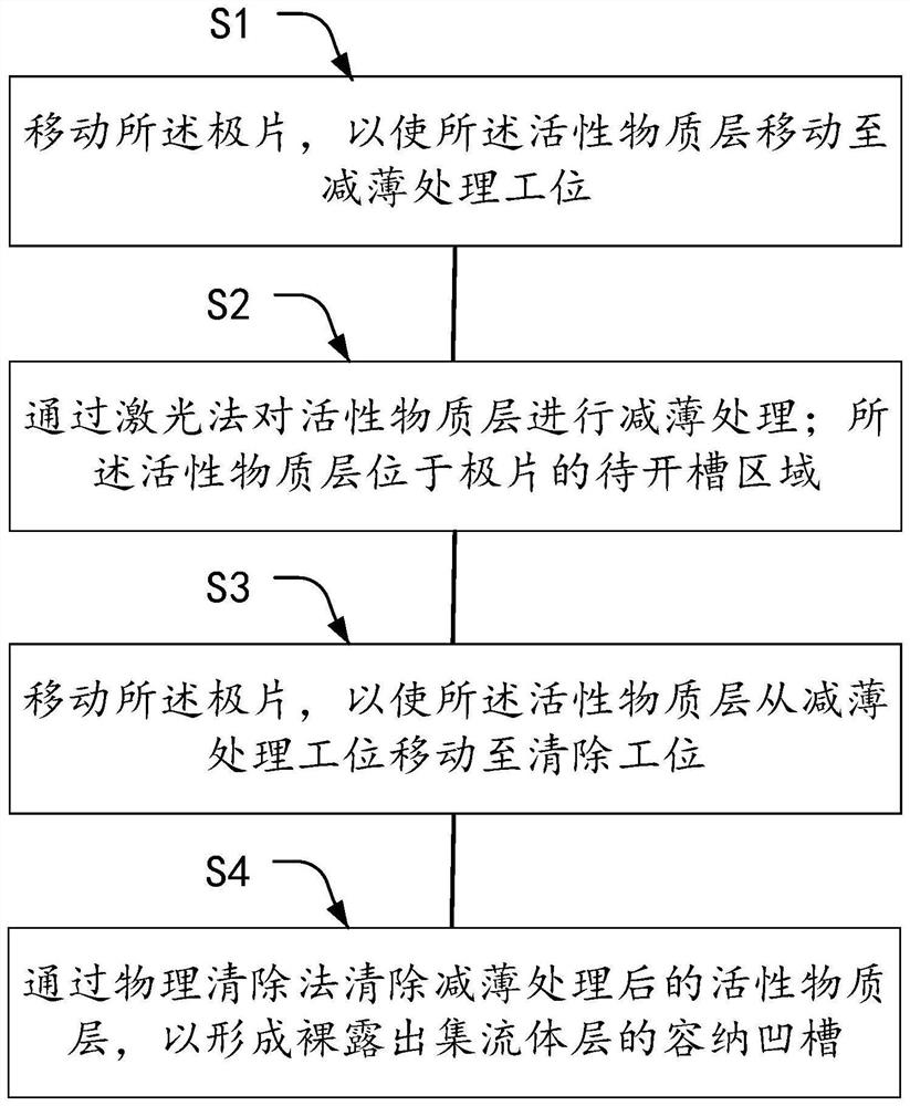
[0039] refer to figure 2 , the pole piece slotting method provided in the second embodiment of the present application includes:
[0040] Step S1: moving the pole piece so that the active material layer moves to a thinning treatment station.
[0041] Step S2: Thinning the active material layer by laser method; the active material layer is located in the area of the pole piece to be grooved.
[0042]Step S3: moving the pole piece so that the active material layer moves from the thinning treatment station to the cleaning station.
[0043] Step S4: removing the thinned active material layer by a physical removal method, so as to form an accommodating groove exposing the current collector layer.
[0044] Wherein, steps S2 and S4 are respectively the same as step S1 and step S2 in the first embodiment, and will not be repeated here.
[0045] The steps S1 and S3 can be carried out with a conveyor belt. Specifically, the pole piece to be slotted is placed on the conveyor belt, ...
no. 3 example
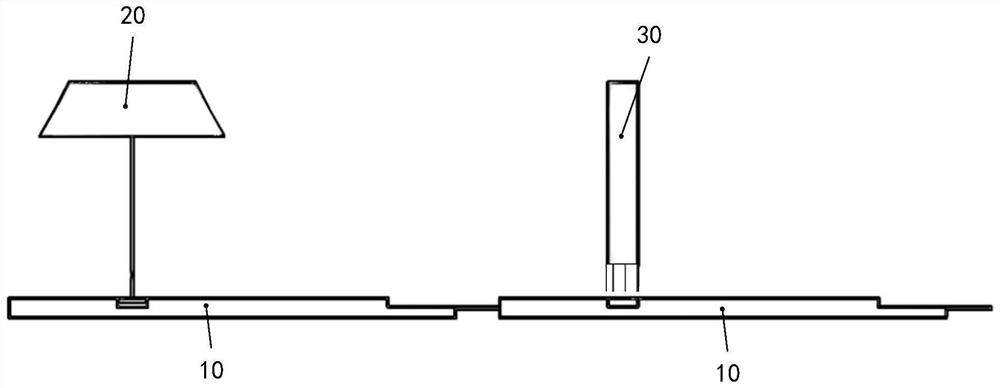
[0049] refer to image 3 , the pole piece 10 slotting device provided in the embodiment of the present application includes a laser 20 and a cleaning tool.
[0050] Wherein, the laser 20 is used for: thinning the active material layer by laser method; the active material layer is located in the region 11 of the pole piece 10 to be grooved. After thinning the active material layer, the range of the thickness H of the active material layer is: 30 microns≥H≥1 micron.
[0051] The cleaning tool is used to: remove the thinned active material layer by physical cleaning method, so as to form the receiving groove 12 exposing the current collector layer.
[0052] In this embodiment, the active material layer in the region 11 to be grooved of the pole piece 10 is removed by using a laser 20 combined with a cleaning tool. First, the laser 20 is used to thin the active material layer, and then the thinned active material layer is removed by a cleaning tool. On the one hand, it can avoi...
PUM
| Property | Measurement | Unit |
|---|---|---|
| Thickness | aaaaa | aaaaa |
| Thickness | aaaaa | aaaaa |
Abstract
Description
Claims
Application Information
 - Generate Ideas
- Intellectual Property
- Life Sciences
- Materials
- Tech Scout
- Unparalleled Data Quality
- Higher Quality Content
- 60% Fewer Hallucinations
Browse by: Latest US Patents, China's latest patents, Technical Efficacy Thesaurus, Application Domain, Technology Topic, Popular Technical Reports.
© 2025 PatSnap. All rights reserved.Legal|Privacy policy|Modern Slavery Act Transparency Statement|Sitemap|About US| Contact US: help@patsnap.com