Mixed membrane biological method anaerobic fermentation reactor for kitchen wastewater, and treatment process thereof

A kitchen wastewater and anaerobic fermentation technology, applied in the direction of anaerobic digestion treatment, etc., can solve the problems of poor three-phase separation effect, low volume loading rate, and poor effluent quality, so as to reduce impact, low investment cost, and improve effluent The effect of water quality

Pending Publication Date: 2020-12-08
银川保绿特生物技术有限公司
View PDF0 Cites 0 Cited by
  • Summary
  • Abstract
  • Description
  • Claims
  • Application Information

AI Technical Summary

Problems solved by technology

This treatment technology has the advantages of simple structure, small investment, convenient operation and management, etc., but at the same time, it also has low volume load rate, low r

Method used


Image

  • Mixed membrane biological method anaerobic fermentation reactor for kitchen wastewater, and treatment process thereof

Examples


Embodiment 1

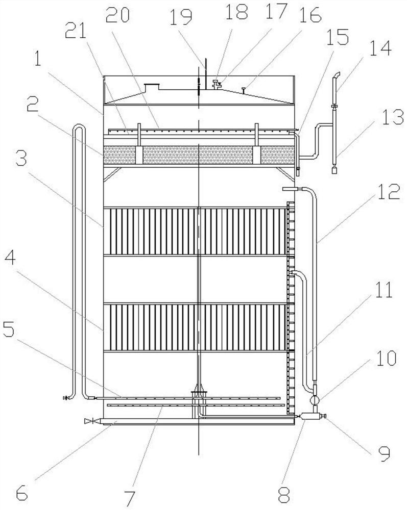
[0036] figure 1 It shows a mixed membrane bio-anaerobic fermentation reactor for kitchen waste water, including a tank body 1, in which three separation zones, a second reaction zone 3, and a first reaction zone are sequentially arranged from top to bottom. Zone 4, biogas gas distribution device 5, water distributor 7 and mud discharge system 6, the mud discharge system includes mud discharge pipes, specifically as in the prior art; the three-phase separation zone 2 is arranged from top to bottom A pressure beam, a three-phase separator and a bottom beam, a water outlet weir 21 is arranged above the pressure beam, and the water outlet weir 21 is connected with an outlet pipe 15 protruding from the outside of the pipe body, and a backwash pipe is arranged above the water outlet weir 21 20; the second reaction zone 3 and the first reaction zone 4 are both biofiller reaction zones, both of which are fixed with biofilm layers through membrane frames, and are connected in series to...

Embodiment 2

[0055] The present invention also provides a treatment process for kitchen waste water mixed membrane biological anaerobic fermentation reactor, the biological fillers in the second reaction zone 3 and the first reaction zone 4 are knotted and tied rope-type biological fillers, The ring-shaped fibers adopting the high-strength polypropylene weaving process form a radial structure, which increases the built-in surface area, makes the sludge in the mixture stay in the first reaction zone 4 and the second reaction zone 3, and granulates the sludge that stays, making the granulation Microorganisms are attached to the surface of the sludge, which effectively improves the biofilm and improves the efficiency of the anaerobic reaction; the treatment process also includes the following steps:

[0056] a. The bottom of the reactor is fed with water, and the granular sludge and the mud-water mixture returned from the gas-liquid separation zone are mixed at the bottom of the reactor, and t...


PUM


Abstract

The invention relates to a mixed membrane biological method anaerobic fermentation reactor for kitchen wastewater, and a process thereof. The mixed membrane biological method anaerobic fermentation reactor comprises a tank body, the tank body is internally provided with an effluent weir, a three-phase separation zone, a second reaction zone, a first reaction zone, a biogas distribution device, a water distributor and a sludge discharge system in sequence from top to bottom; the second reaction zone and the first reaction zone are both biological filler reaction zones; the biogas distribution device is provided with a gas inlet pipe; the water distributor is communicated with a water inlet mixer outside the tank body, and the water inlet mixer is communicated with a water inlet pipe; a biogas collecting pipe is arranged at the top of the tank body and is connected with the gas inlet pipe; an upper circulating pipe and a middle circulating pipe are further included, and the middle circulating pipe is further communicated with the water inlet mixer; and the wastewater in the tank body reaches the water inlet mixer through the middle circulating pipe, is mixed and then returns to the tank body through the water distributor to finish circulation. The reactor and the technology can be used for treating the kitchen leachate with high concentration and high suspended solids.

Description

technical field [0001] The invention belongs to the technical field of kitchen waste treatment, and in particular relates to a mixed-type membrane biological method anaerobic fermentation reactor for kitchen waste water and a treatment process thereof. Background technique [0002] At present, my country's food waste treatment technologies mainly include anaerobic digestion, aerobic treatment and feed. Among them, anaerobic digestion is the mainstream technology, and many people admire it because of its mature technology. [0003] The anaerobic process refers to the use of garbage to produce biogas and convert it into electricity and gas, and to perform secondary fermentation and composting on the residue produced in the anaerobic digestion tank. Compared with direct aerobic composting, it can reduce the occupied area, and the quantity of fertilizer is small, and the products are diversified. [0004] The biogas produced by the anaerobic fermentation and degradation of foo...

Claims


Application Information

Patent Timeline
IPC IPC(8): C02F3/28
CPCC02F3/28
Inventor 曹健仪沈光秀李宁森杨来平曹茹茗倪建利宋涛马军杨茂森李晶郑佳赛
Owner 银川保绿特生物技术有限公司
Why Eureka
Try Eureka