Machine vision illumination lens for generating customized light spots and design method of machine vision illumination lens

A machine vision and lens technology, used in lighting and heating equipment, lighting installations, design optimization/simulation, etc., to solve problems such as target image highlights, shadows, and feature mis-segmentation

Active Publication Date: 2020-12-08
FUDAN UNIV
View PDF3 Cites 2 Cited by
  • Summary
  • Abstract
  • Description
  • Claims
  • Application Information

AI Technical Summary

Problems solved by technology

[0003] The present invention provides a machine vision lighting lens design method for generating customized light spots, aiming at detecting uniform lighting spots of a specific shape on the target surface, and Different irradiances are generated in the area to solve the problems of high light, shadow and wrong segmentation of features in complex detection target images in the current machine vision system

Method used


Image

  • Machine vision illumination lens for generating customized light spots and design method of machine vision illumination lens
  • Machine vision illumination lens for generating customized light spots and design method of machine vision illumination lens
  • Machine vision illumination lens for generating customized light spots and design method of machine vision illumination lens

Examples


Embodiment Construction

[0062] The technical details of the present invention will be further described below in conjunction with the accompanying drawings.

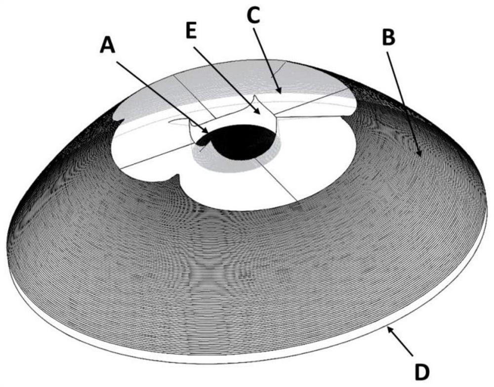
[0063] figure 1 It is a schematic diagram of the lighting lens of the present invention, and the lighting lens specifically includes a transmission aspheric surface A, a total internal reflection aspheric surface B, a curved bottom surface C, a lens exit surface D and a transmission cylindrical surface E; the surface shape of the lens exit surface D As a plane, the LED light passes through the transmission aspheric surface A, the total internal reflection aspheric surface B, the bottom curved surface C and the transmission cylindrical surface E after light distribution, and finally exits from the lens exit surface D to the target surface.

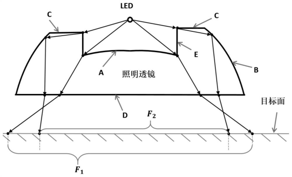
[0064] figure 2 It is a schematic cross-sectional view of the lighting lens according to the present invention. The transmission aspheric surface A distributes the light emitted by the LED at a small angle...


PUM


Abstract

The invention belongs to the technical field of illumination design and machine vision, and particularly relates to a design method of an illumination lens for improving a vision detection system. According to the design method, a composite structure is adopted by a light distribution lens, two aspheric surfaces respectively perform total internal reflection light distribution and transmission light distribution on emergent light of a light source, so that the uniformity of irradiation distribution on a target surface is ensured, and bottom curved surfaces are used for customizing the shapes of uniform light spots on the target surface; and two groups of differential algebraic equations and a group of nonlinear equations are established in combination with the solid geometry relationship of the lens, and numerical solutions of the equations are processed into an illumination lens three-dimensional model and imported into optical tracing software for simulation. According to the designmethod, the uniform customized-shaped light spots can be generated, illumination can be customized in a targeted manner, the irradiation uniformity and the luminous flux utilization rate are high, anddifferent irradiance can be generated in different areas in the target surface according to the reflectivity design of a detection target, so that highlight or shadows in visual detection are inhibited, and the image quality of the visual detection is improved.

Description

technical field [0001] The invention belongs to the technical field of lighting design and machine vision, and in particular relates to a lighting lens design method for improving a visual inspection system, which can not only generate uniform light spots with customized shapes on the target surface, but also produce different light spots in different regions of the target surface. radioactivity. Background technique [0002] There are many kinds of detection targets for machine vision, which often contain multiple materials or have complex structures. Different materials have different reflectivities, and their ability to reflect illumination light is different. Therefore, the simple circle produced by the existing machine vision lighting system Uniform light spots can easily lead to highlights or shadows in the camera image; in addition, the detection target itself or a certain part may have a specific shape, such as a rectangle and a polygon, and a simple circular uniform...

Claims


Application Information

Patent Timeline
Patent Type & Authority Applications(China)
IPC IPC(8): F21V5/04G02B27/00G03B15/02G06F30/20G06F17/13
CPCF21V5/04G03B15/02G02B27/0012G06F30/20G06F17/13
Inventor 孔令豹孙翔
Owner FUDAN UNIV
Why Eureka
Try Eureka