
Phase change energy storage strengthening device with built-in ultrasonic generator

A phase-change energy storage and strengthening device technology, applied in the direction of heat exchanger types, indirect heat exchangers, heat exchange equipment, etc. Involving heat and mass transfer enhancement and other issues, to achieve good temperature uniformity and temperature control capabilities, eliminate conduction losses, and improve the effect of energy storage efficiency

Active Publication Date: 2020-12-08
XI AN JIAOTONG UNIV
View PDF25 Cites 0 Cited by
  • Summary
  • Abstract
  • Description
  • Claims
  • Application Information

AI Technical Summary

Problems solved by technology

However, the above-mentioned documents do not fully disclose the specific structure type of the ultrasonic generating module, and the container structure of the phase change material is also different.
Moreover, none of the above-mentioned documents explicitly mentions that the ultrasonic generating module has multiple built-in forms, nor does it involve the enhancement of heat and mass transfer in the hard-to-melt solid phase region of the energy storage unit
[0005] Chinese patent application CN102384605 and Chinese patent application CN2861137 both disclose the structure of the built-in ultrasonic generator, but they are all used in the field of single-phase heat exchange, and the complex two-phase heat exchange problems existing in the phase change energy storage unit, such as local heat exchange Inequality

Method used


Image

  • Phase change energy storage strengthening device with built-in ultrasonic generator
  • Phase change energy storage strengthening device with built-in ultrasonic generator
  • Phase change energy storage strengthening device with built-in ultrasonic generator

Examples


Embodiment Construction

[0034] The technical scheme of the present invention will be clearly and completely described below in conjunction with the accompanying drawings, and the described embodiments are part of the embodiments of the present invention, rather than all embodiments; based on the embodiments of the present invention, those of ordinary skill in the art can All other embodiments obtained under the premise of no creative work belong to the protection scope of the present invention.

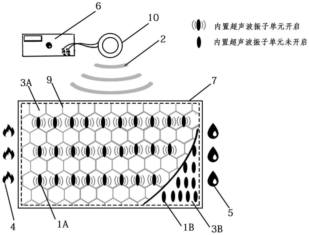
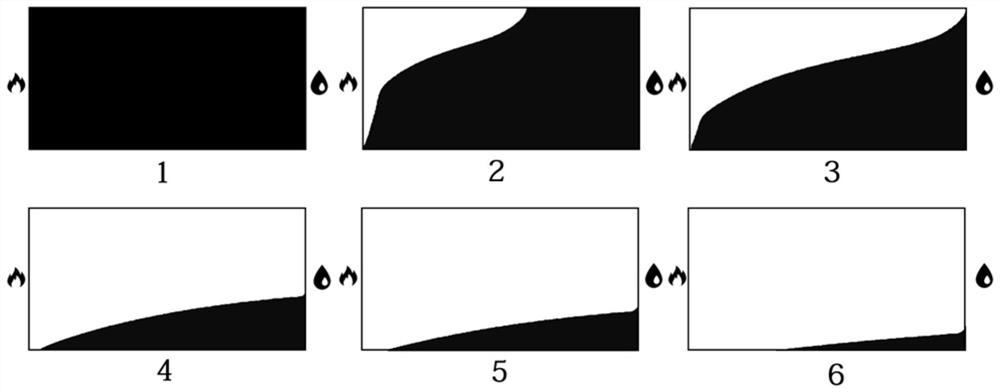
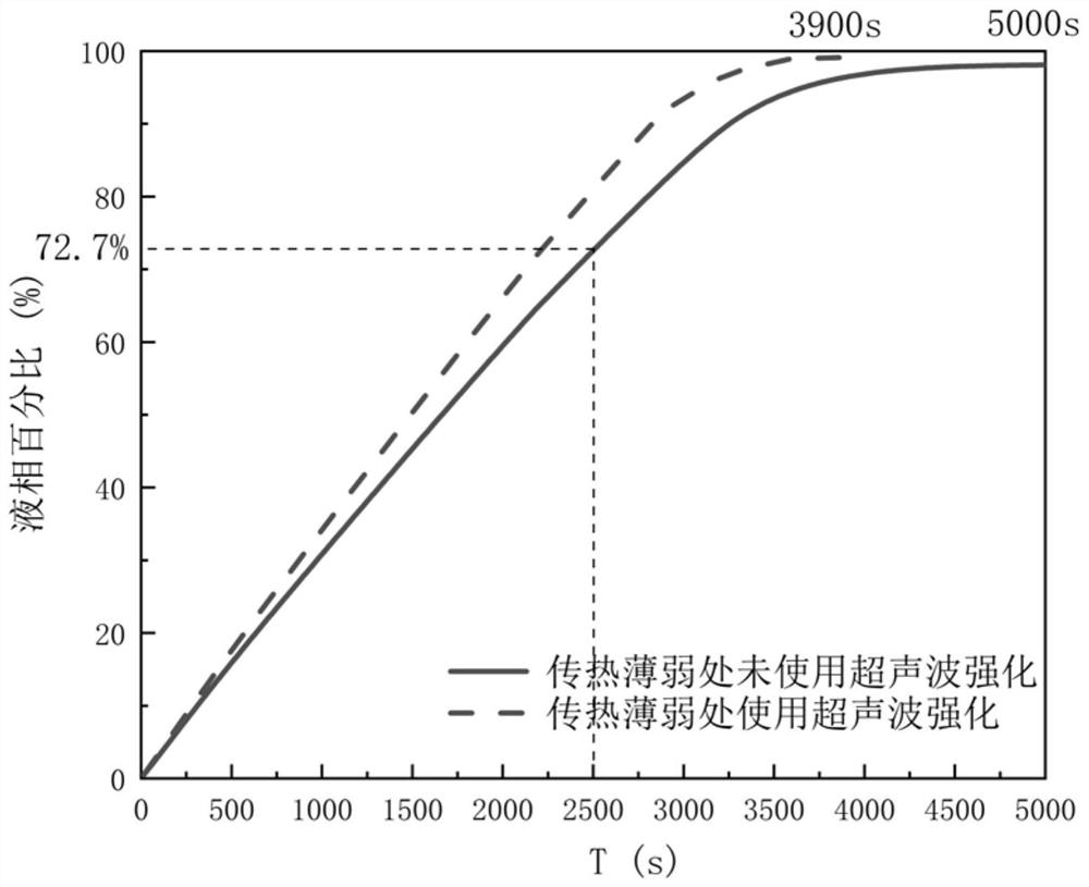
[0035] In this paper, a qualitative numerical simulation is carried out for the phenomenon that there is a hard-to-melt solid phase region in the melting of phase change materials, taking a three-dimensional cubic heat storage unit of 60mm*120mm*100mm as an example. Simulation results with figure 2 , image 3 exhibit. figure 2 It is a schematic diagram of the melting process of the phase change material without ultrasonic waves in the hard-to-melt solid phase region of the energy storage unit, image 3 ...


PUM


Abstract

The invention relates to a phase change energy storage strengthening device with a built-in ultrasonic generator. The device comprises an ultrasonic generation module and a phase change energy storagemodule, wherein the ultrasonic generation module comprises a built-in ultrasonic vibrator unit, an external wireless charging emitter and an external power supply, and the built-in ultrasonic vibrator unit is composed of a temperature sensing switch, an ultrasonic generator and a wireless charging receiver; and the phase change energy storage module comprises a closed shell, a heating surface, acooling surface, a phase change material and a porous material. The built-in ultrasonic vibrator unit has the following two arrangement requirements that 1, the built-in ultrasonic vibrator unit is arranged in the middle of the interior of the porous material so as to strengthen a full-field phase change material; and 2, the built-in ultrasonic vibrator unit is arranged in a solid-phase area whichis difficult to melt at the junction of the lower end of the cooling surface of the device and the bottom of the closed shell, so as to specially strengthen a local non-uniform heat exchange part. Particularly, the start-stop working condition of the built-in ultrasonic vibrator unit should be automatically controlled according to the real-time melting condition of the phase change material.

Description

technical field [0001] The invention belongs to the field of enhanced energy storage and heat exchange, and in particular relates to a phase-change energy storage enhancement device with a built-in ultrasonic generator for wireless power supply and its control logic, and performs targeted optimization on dead angles of heat exchange of phase-change energy storage materials. Background technique [0002] The intermittence and volatility of renewable energy are the main constraints to achieve stable energy supply. The phase change heat storage system uses phase change materials to absorb or release latent heat to store heat during the phase change process, and can convert fluctuating energy input into relatively stable energy output to solve the mismatch between energy supply and demand in terms of time, space and intensity. It can improve the stability and reliability of renewable energy, and is widely used in passive buildings, solar thermal utilization, waste heat recovery ...

Claims


Application Information

Patent Timeline
IPC IPC(8): F28D20/02F28F13/10
CPCF28D20/021F28D20/028F28F13/10Y02E60/14
Inventor 王秋旺蔡凌霄魏捷司天誉钱琛怿郑笑天崔卫
Owner XI AN JIAOTONG UNIV
Features
  • Generate Ideas
  • Intellectual Property
  • Life Sciences
  • Materials
  • Tech Scout
  • Unparalleled Data Quality
  • Higher Quality Content
  • 60% Fewer Hallucinations
Learn More