
System and method for imaging recovery through dynamic scatterers

A scatterer and dynamic technology, applied in image enhancement, image data processing, instruments, etc., can solve the problems of low fidelity of imaging restoration, complex and time-consuming restoration algorithm, and achieve high universality, low difficulty, and experimental system simple effect

Active Publication Date: 2020-12-08
JINAN UNIVERSITY
View PDF3 Cites 0 Cited by
  • Summary
  • Abstract
  • Description
  • Claims
  • Application Information

AI Technical Summary

Problems solved by technology

[0005] Based on this, it is necessary to provide a system and method for imaging recovery through dynamic scatterers to solve the problems of complex and time-consuming recovery algorithms and low fidelity of imaging recovery.

Method used


Image

  • System and method for imaging recovery through dynamic scatterers
  • System and method for imaging recovery through dynamic scatterers
  • System and method for imaging recovery through dynamic scatterers

Examples


Embodiment 1

[0037] see figure 1 , one A system for recovering imaging through a dynamic scatterer, including: a light source and an adjustment unit, a dynamic scatterer, and an imaging observation unit; the light source and the adjustment unit include: a light source, an attenuation sheet, and a beam expander; when imaging, a sample is set in a beam expander Between the light source and the dynamic scatterer; the light source is used to output the collimated monochromatic laser beam; the attenuation sheet is used to reduce the intensity of the monochromatic laser beam; The light spot will not be oversaturated, thus protecting the CCD camera. The beam expander is used to adjust the beam diameter of the monochromatic laser beam passing through the attenuation sheet, so that the beam diameter of the monochromatic laser beam exceeds the pattern to be measured on the sample, so that the area where the pattern to be measured is located is in the beam; the dynamic scatterer is located at The ...

Embodiment 2

[0052] Use the solution prepared according to 20ml of purified water and 4600μl of pure milk as the dynamic scattering medium to recover the pattern to be tested. Before the experiment, a solution of pure milk and purified water was prepared in proportion. Add 20ml of pure water to the test tube, then add 4600μl of pure milk to the test tube with a pipette gun, and stir to make the two fully mixed.

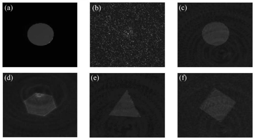
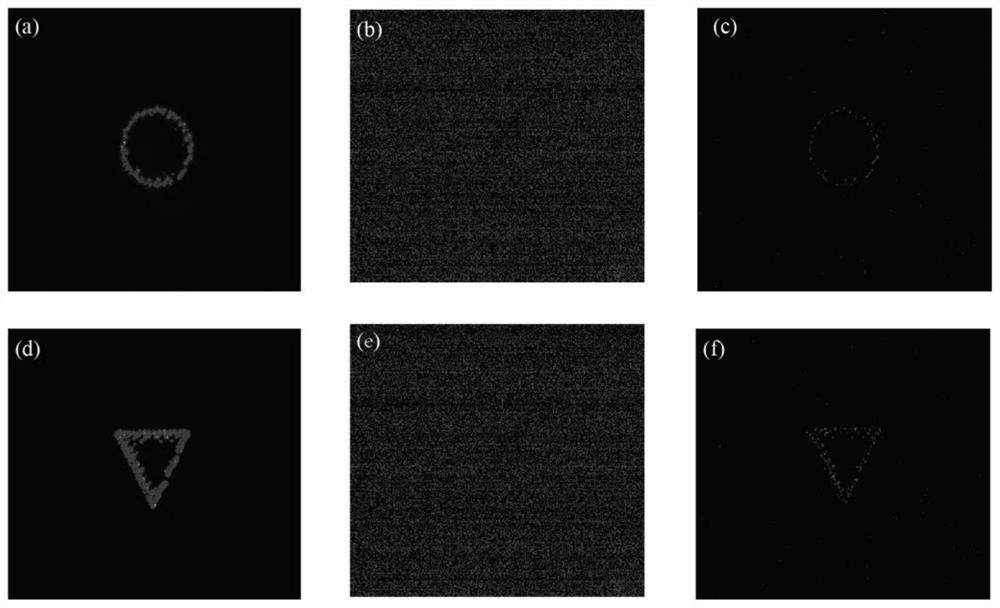
[0053] Turn on the collimated laser with a wavelength of 532nm, adjust the helical axis of the three-dimensional translation stage, so that the expanded laser beam is vertically incident on the selected circle (the figure to be measured has triangles and circles), and adjust the CCD and lens distance, so that the circle presents a clear image on the CCD, save the picture as the original picture, such as image 3 (a) shown. Use a needle to drop the prepared milk solution into a cuvette (3.5mm×12.5mm×45mm) with an optical path of 1mm. Place the cuvette at a distance of 50mm from t...


PUM


Abstract

The invention relates to a system and method for imaging recovery through a dynamic scatterer. The system comprises a light source and adjusting unit, the dynamic scatterer and an imaging observationunit. The light source and adjusting unit comprises a light source, an attenuation sheet and a beam expander; during imaging, a sample is arranged between the beam expander and the dynamic scatterer;the light source is used for outputting a collimated monochromatic laser beam; the attenuation sheet is used for weakening the light intensity of the single-color laser beam; the beam expander is usedfor adjusting the beam diameter of the single-color laser beam passing through the attenuation sheet, so the beam diameter of the single-color laser beam exceeds a to-be-measured pattern on the sample; the dynamic scatterer is positioned behind the sample engraved with the to-be-measured pattern and is used for loading a random phase and generating speckles; and the image acquisition unit is usedfor acquiring and recording the image of the graph to be measured and the speckle pattern passing through the dynamic scatterer. According to the invention, speckle superposition is carried out on the collected speckle pattern by using a simple superposition algorithm, and correction and optimization are carried out, so that the fidelity of the recovered image is very high.

Description

technical field [0001] The invention relates to the field of scatter imaging, in particular to a system and method for imaging recovery through dynamic scatterers. Background technique [0002] In life, scattering phenomena can be seen everywhere, such as blue sky and white clouds, mountains and rivers, water curtain movies, etc., which show us the colorful life. However, the scattering phenomenon will also cause us some troubles in some aspects, for example, the low visibility in foggy weather brings hidden dangers to traffic safety; in biomedical diagnosis and treatment, it is difficult to image the cells and tissues under the skin; and, Cause obstacles to the tracking of aircraft and missiles behind the clouds, etc. The existence of these haze, skin tissue, smoke, clouds and other random scattering media prevents us from directly seeing the target objects hidden behind these scattering media. In the traditional imaging concept, as long as an object that satisfies the ob...

Claims


Application Information

Patent Timeline
Patent Type & Authority Applications(China)
IPC IPC(8): G06T5/00G06T5/50
CPCG06T5/50G06T5/00
Inventor 付神贺莫广翠陈振强李真尹浩
Owner JINAN UNIVERSITY
Learn More