
Laser-induced free-form surface periodic nanostructure pattern and coloring method

A nanostructure and laser-induced technology, applied in nanotechnology, microstructure technology, microstructure devices, etc., can solve the problems of response speed, degree of automation and precision that cannot be satisfied at the same time, inconsistent laser incident direction, and changes in processing parameters, etc., to achieve Clear coloring effect, ensure high efficiency and high precision, and ensure the effect required by processing

Inactive Publication Date: 2020-12-11
EAST CHINA NORMAL UNIV
View PDF7 Cites 5 Cited by
  • Summary
  • Abstract
  • Description
  • Claims
  • Application Information

AI Technical Summary

Problems solved by technology

However, this technology can select the appropriate distance to realize the seamless connection of periodic stripes on the two-dimensional plane, but for the three-dimensional free-form surface, the seamless splicing is relatively difficult, and traditional computer-aided manufacturing (CAM) software cannot realize it.
[0003] In the existing technology, the scanning galvanometer is used to realize the function of operating periodic stripes in sub-regions in the free-form surface, but there is a problem of inconsistency in the incident direction of the laser in a scanning region, and many processing parameters change slightly
Polarization devices usually cannot achieve parallel control with lasers and three-dimensional motion systems, and the response speed, degree of automation and precision often cannot meet the requirements at the same time.

Method used


Image

  • Laser-induced free-form surface periodic nanostructure pattern and coloring method
  • Laser-induced free-form surface periodic nanostructure pattern and coloring method
  • Laser-induced free-form surface periodic nanostructure pattern and coloring method

Examples


Embodiment 1

[0047] 1) Build a laser synchronous polarization control processing system

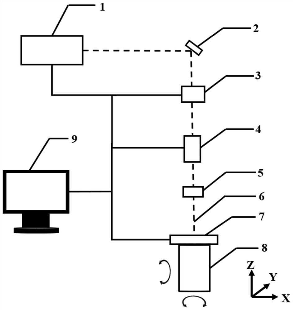
[0048] See attached figure 1 , build a laser synchronous polarization control processing system, so that the laser beam 6 converges on the sample stage 7 through the optical path of the lens system 2, the half-wave plate and the liquid crystal polarization rotator 3, the dynamic beam expander 4 and the lens 5. After converging, the spot diameter is 24μm, and the energy density is 7.52J / cm 2 ;

[0049] 2) Set processing conditions

[0050] Control the energy flux density of the laser to 7.52J / cm 2 , the scanning speed is 7mm / s, and the spot diameter of the laser beam converging on the sample surface is 24μm, which ensures that the formed stripes are arranged regularly, with high definition and good coloring effect.

[0051] 3) Synchronous polarization control technology to prepare periodic nanostructure patterns and coloring on free-form surfaces

[0052] The stainless steel sample was placed in e...


PUM

PropertyMeasurementUnit
diameteraaaaaaaaaa

Abstract

The invention discloses a laser-induced free-form surface periodic nanostructure pattern and coloring method which is characterized in that periodic sub-wavelength stripes are prepared on a plane or acurved surface by utilizing a built laser synchronous polarization control processing system and a computer-aided manufacturing program and through accurately controlling mechanical motion and laserirradiation parameters, so that the synchronous control over a laser polarization direction and the accurate control over a stripe direction are achieved, and different coloring effects are achieved through different stripe directions. Compared with the prior art, the laser-induced free-form surface periodic nanostructure pattern and coloring method provided by the invention has the advantages that different coloring effects are achieved by utilizing the influence of different laser energy flow densities and scanning rates on stripe formation, and particularly, the method has the advantages ofobvious advantages, high precision, convenience in operation, economy and high efficiency in the aspect of preparing the complex color patterns with clear and bright periodic nanostructures on the curved surface.

Description

technical field [0001] The invention relates to the technical field of laser micro-nano manufacturing, in particular to a laser-induced free-form surface periodic nanostructure pattern and coloring method. Background technique [0002] People have experienced laser-induced periodic surface structure for more than half a century, and its functional application fields include: anti-reflection, anti-counterfeiting, coloring of material surface, modification of material surface wettability, control of cell reaction, change of tribological properties, change of colony or cell growth rate, etc. However, this technology can select the appropriate distance to realize the seamless connection of periodic stripes on the two-dimensional plane, but for the three-dimensional free-form surface, the seamless splicing is relatively difficult, and traditional computer-aided manufacturing (CAM) software cannot realize it. [0003] In the prior art, scanning galvanometers are used to realize t...

Claims


Application Information

Patent Timeline
Patent Type & Authority Applications(China)
IPC IPC(8): B23K26/062B23K26/064B23K26/362B23K26/70B82Y40/00
CPCB23K26/009B23K26/0643B81C1/00492B81C2201/0143B82Y40/00B23K26/0821
Inventor 蒋其麟刘聚坤冯朝鹏陈龙曹凯强贾天卿孙真荣
Owner EAST CHINA NORMAL UNIV
Learn More