
Polishing machine for bucket tooth casting

A technique for polishing machines and bucket teeth, which is applied in grinding/polishing equipment, grinding/polishing safety devices, and machine tools suitable for grinding the edge of workpieces, etc. It can solve problems such as troublesome operation and low efficiency, and achieve effective collection, Effect of increasing polishing efficiency

Inactive Publication Date: 2020-12-11
余清河
View PDF9 Cites 0 Cited by
  • Summary
  • Abstract
  • Description
  • Claims
  • Application Information

AI Technical Summary

Problems solved by technology

[0004] Aiming at the deficiencies in the prior art, the object of the present invention is to provide a polishing machine for bucket tooth casting, to solve the problem that in the process of polishing the bucket teeth in the existing polishing machine, most of the fixing methods for the bucket teeth are clamping type, This method needs to change the clamping angle during the processing, so that the edge of the bucket tooth can be polished in place. This processing method is not efficient and the operation is more troublesome.

Method used


Image

  • Polishing machine for bucket tooth casting
  • Polishing machine for bucket tooth casting
  • Polishing machine for bucket tooth casting

Examples


no. 1 example

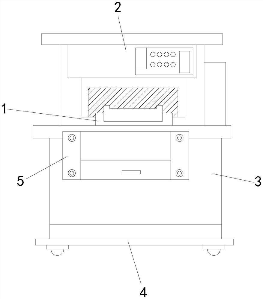
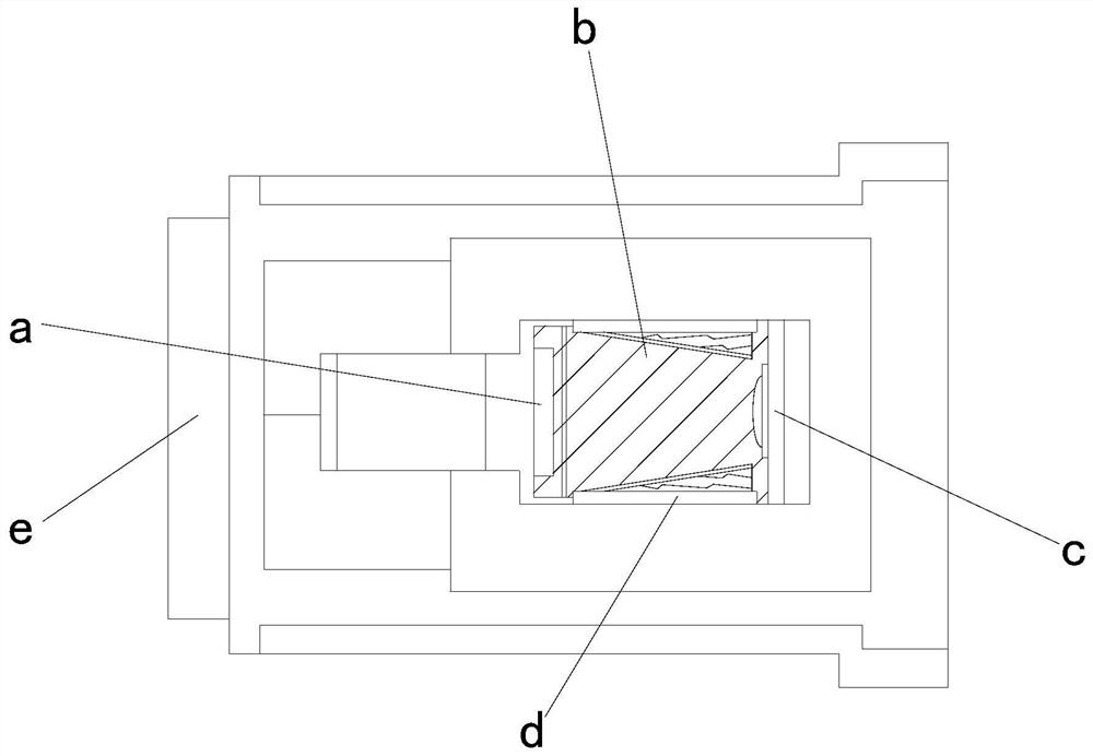
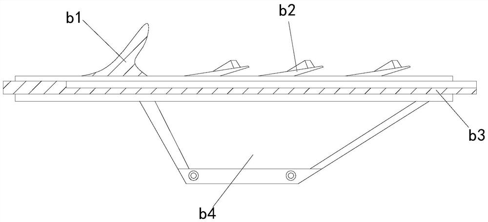
[0025] see Figure 1-Figure 3 , the present invention provides a technical solution for a polishing machine for bucket tooth casting: its structure includes: a polishing tank body 1, a console 2, a loading frame 3, a moving base 4, and a power unit 5, and the moving base 4 is installed on the loading frame 3 Below and locked with the loading frame 3, the upper end of the loading frame 3 is embedded with a power device 5, and the upper end of the power device 5 is provided with a polishing tank body 1, and the polishing tank body 1 is fastened with the power device 5, and the polishing tank body 1 is connected with the power device 5. A console 2 is provided above the tank body 1 and is electrically connected to the console 2. The polishing tank body 1 includes a polishing sleeve device a, a contact plate device b, a buffer plate c, a stabilizing splint d, and a loader compartment e. The splint d is installed on both sides of the contact plate device b and fastened with the con...

no. 2 example

[0029] see Figure 4-Figure 5 , the present invention provides a technical solution for a polishing machine for bucket tooth casting: its structure includes: the polishing sleeve device a includes a polishing disc device a1, a turning wheel a2, a telescopic rod group a3, a partition cover a4, and the telescopic rod group a3 Installed on the outer side of the turning wheel a2 and fastened with the turning wheel a2, the inner side of the turning wheel a2 is provided with a polishing disc device a1, the polishing disc device a1 is buckled with the turning wheel a2, and the upper end of the polishing disc device a1 is locked. Divider cover a4.

[0030] The polishing disc device a1 includes a starting wheel a11, a linkage frame a12, a mating frame a13, an upper throwing wheel a14, and a polishing side wheel set a15. The outer side of the linkage frame a12 is provided with an upper throwing wheel a14, the side of the linkage frame a12 is provided with a mating frame a13, and the in...


PUM


Abstract

The invention discloses a polishing machine for bucket tooth casting. The polishing machine structurally comprises a polishing groove machine body, a control table, a loading frame, a movable base anda power device. The movable base is arranged below the loading frame and is in locking connection with the loading frame. The power device is embedded in the upper end of the loading frame. When theequipment is used, through the arranged polishing groove mechanism, the problems that in the process that the polishing machine polishes bucket teeth, most of the fixing manners of the bucket teeth are clamping manners, in the manner, the clamping angle needs to be changed in the machining process, then the edges of the bucket teeth can be polished in place, the machining manner is not high in efficiency, and the operation is troublesome can be solved, the equipment is matched through a specific polishing sleeve device, then the sleeving type structure can sleeve the bucket teeth to wrap the periphery of the bucket teeth, the polishing efficiency of the bucket teeth is improved, meanwhile, through mutual cooperation of contact plate devices, polished scrap iron can be effectively collected, and more convenience is achieved.

Description

technical field [0001] The invention relates to a polishing machine for bucket tooth casting, which belongs to the field of polishing machine equipment. Background technique [0002] Excavator bucket teeth are an important part of the excavator. Similar to human teeth, they are also vulnerable parts. They are combined bucket teeth composed of tooth seats and tooth tips. The two are connected by pins, and the bucket teeth are in the process of manufacturing , the edges need to be polished. [0003] The existing technology has the following disadvantages: in the process of polishing the bucket teeth by the polishing machine, the fixation method for the bucket teeth is mostly clamping, which requires changing the clamping angle during the processing, so that the bucket teeth can be fixed The edge is polished in place, this kind of processing method is not efficient and the operation is more troublesome. Contents of the invention [0004] Aiming at the deficiencies in the pr...

Claims


Application Information

Patent Timeline
IPC IPC(8): B24B9/04B24B41/02B24B41/04B24B41/06B24B47/12B24B47/22B24B55/12
CPCB24B9/04B24B41/02B24B41/04B24B41/06B24B47/12B24B47/22B24B55/12
Inventor 余清河
Owner 余清河
Learn More