
Stirring equipment for pneumonia vaccine production

A technology for vaccine production and stirring equipment, applied in the directions of dissolving, mixer, chemical instrument and method, can solve the problems of low mixing efficiency of raw materials, inconvenient use, poor mixing effect, etc., to improve mixing efficiency, avoid raw material accumulation, improve The effect of blending

Inactive Publication Date: 2020-12-15
AB&B BIO TECH CO LTD JS
View PDF5 Cites 1 Cited by
  • Summary
  • Abstract
  • Description
  • Claims
  • Application Information

AI Technical Summary

Problems solved by technology

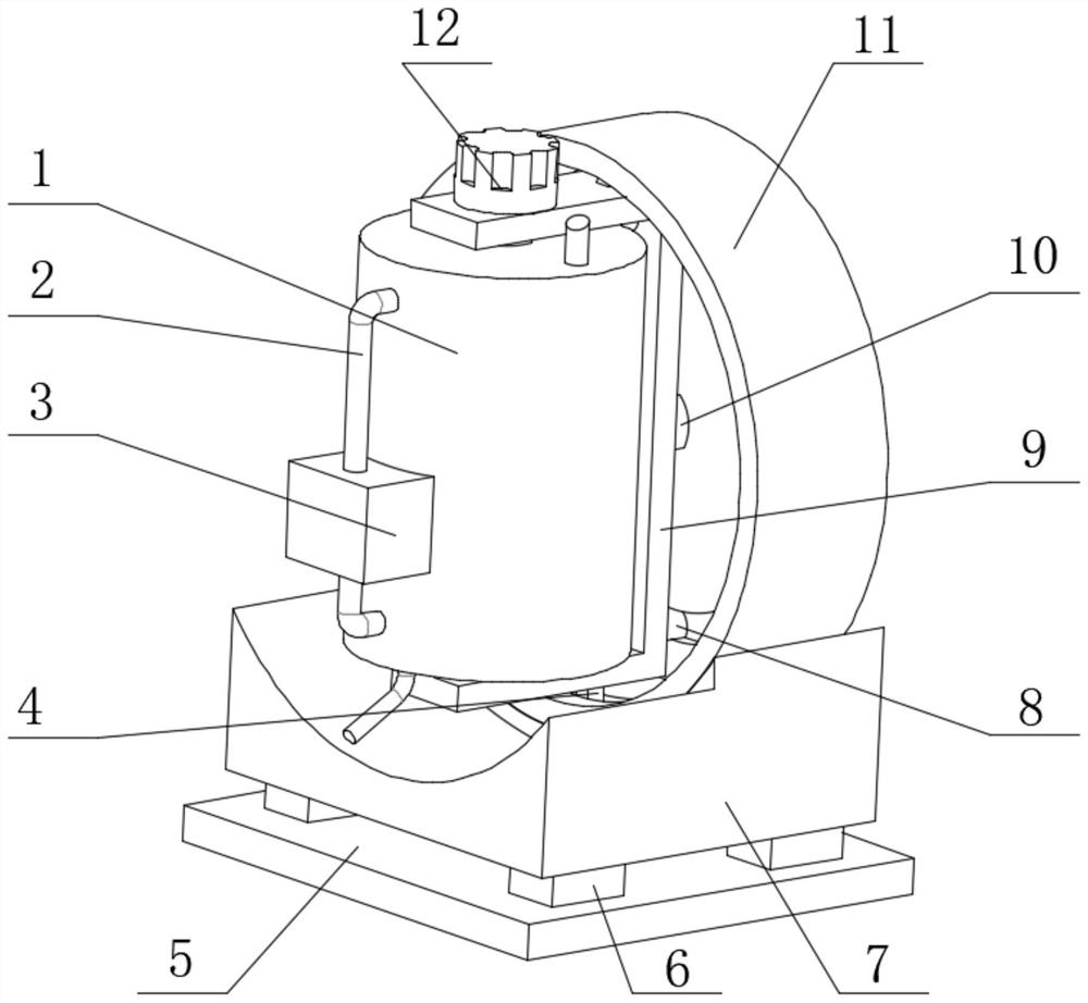
[0003] In the production process of pneumonia vaccine, the raw materials need to be heated, mixed and stirred, but the mixing efficiency of the current mixing device for raw materials is low, and the mixing effect is poor, which is not convenient for people to use. Therefore, a kind of mixing equipment for the production of pneumonia vaccine is urgently needed. solve the above problems

Method used


Image

  • Stirring equipment for pneumonia vaccine production
  • Stirring equipment for pneumonia vaccine production
  • Stirring equipment for pneumonia vaccine production

Examples


Embodiment 1

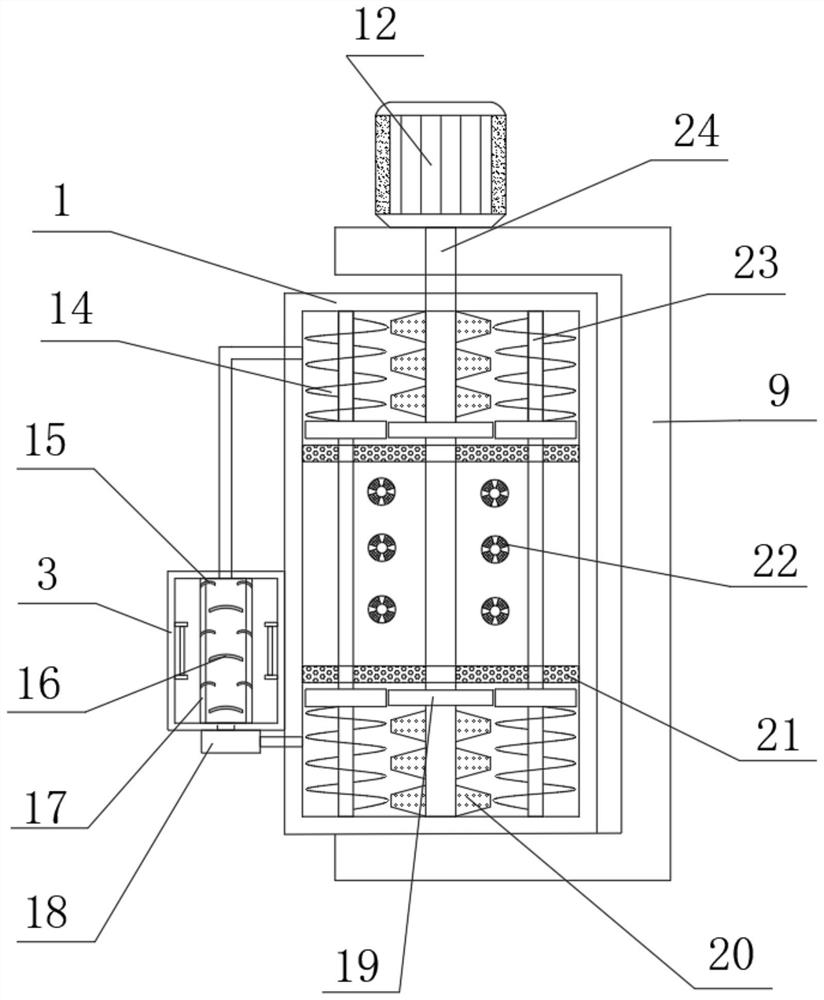
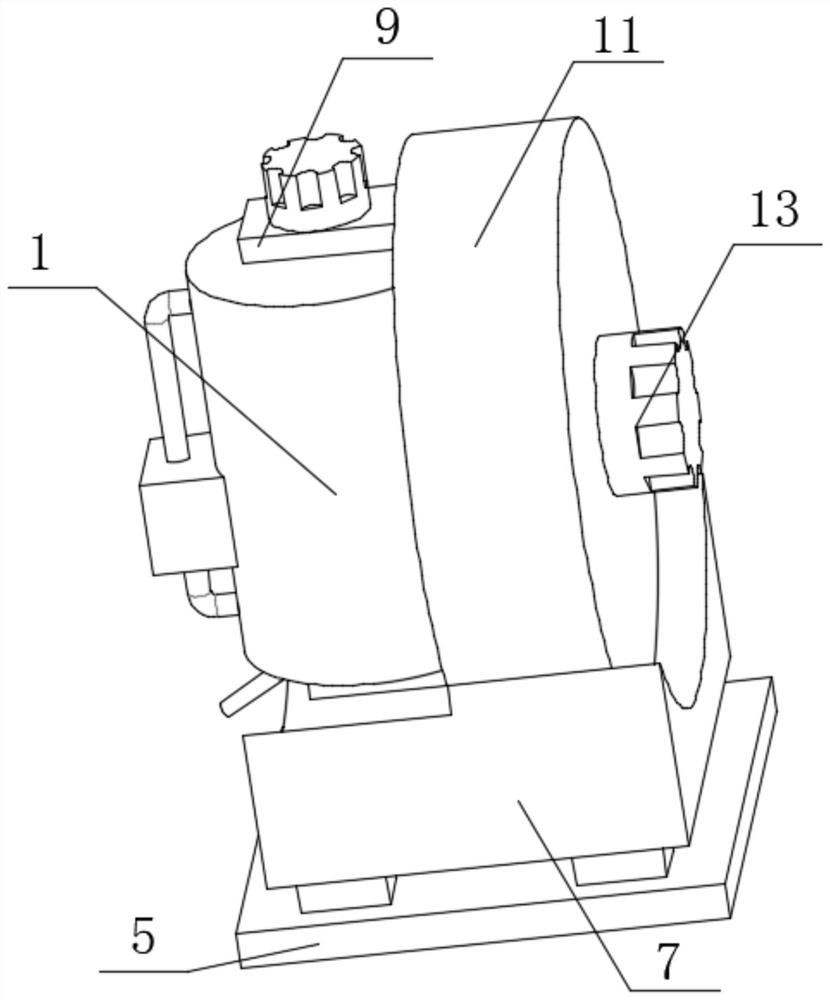
[0028] refer to Figure 1-4 , a mixing device for pneumonia vaccine production, comprising a base 7, an installation housing 11 is installed on one side of the top outer wall of the base 7, and a motor 13 is installed on the outer wall of the installation housing 11, and an output is installed on the outer wall of the output end of the motor 13. Shaft 10, and a mounting bracket 9 is installed on the outer wall of one side of the output shaft 10, and the inner wall of the installation housing 11 is provided with a first limiting circular groove, and the top and bottom inner walls of the first limiting circular groove are provided with a first limiting rod 4. The other end of the first limit rod 4 is fixedly connected to the outer wall of the corresponding installation frame 9, and the inner wall of one side of the installation housing 11 is provided with a second limit circular groove, and the inner wall of the second limit circular groove is slidingly connected with two The se...

Embodiment 2

[0032] refer to Figure 1-5 , a kind of stirring equipment for pneumonia vaccine production also includes the same dispersing rod 26 installed on the inner walls of both sides of the tapered hole.

[0033] Working principle: Compared with embodiment 1, through the dispersing rod 26 arranged inside the tapered hole in the dispersing ball 22, the dispersing rod 26 can disperse and mix the raw materials entering the tapered hole, further improving the mixing of the stirring device. effect, making the device more perfect.


PUM


Abstract

The invention discloses stirring equipment for pneumonia vaccine production. The equipment comprises a base, a mounting shell is mounted on one side of the outer wall of the top of the base, a motor is mounted on the outer wall of one side of the mounting shell, an output shaft is mounted on the outer wall of one side of the output end of the motor, and a mounting frame is mounted on the outer wall of one side of the output shaft; and a first limiting circular groove is formed in the circumferential inner wall of the mounting shell, and first limiting rods are arranged on the inner walls of the top and the bottom of the first limiting circular groove correspondingly. According to the stirring equipment, through a rotating shaft and a driving gear arranged on a servo motor, a circular shafton a driven gear can be driven to rotate, spiral blades on the circular shaft mix raw materials in the stirring shell, the rotating directions of the spiral blades at the top and the bottom of the circular shaft are opposite, the raw materials can be moved to the middle, and the sufficient mixing is achieved; the accumulation of the raw materials is avoided, trapezoidal stirring plates on the outer wall of the circumference of the rotating shaft are used for mixing the raw materials again, so that the mixing efficiency is improved.

Description

technical field [0001] The invention relates to the technical field of vaccine production, in particular to a stirring device for pneumonia vaccine production. Background technique [0002] Vaccines refer to biological products made from various pathogenic microorganisms for vaccination. The vaccines made of bacteria or spirochetes are also called bacterins. Vaccines are divided into live vaccines and dead vaccines. Commonly used live vaccines include BCG, polio, measles, and plague. Commonly used inactivated vaccines include whooping cough vaccine, typhoid fever vaccine, meningococcal meningitis vaccine, and cholera vaccine. [0003] In the production process of pneumonia vaccine, the raw materials need to be heated, mixed and stirred, but the mixing efficiency of the current mixing device for raw materials is low, and the mixing effect is poor, which is not convenient for people to use. Therefore, a kind of mixing equipment for the production of pneumonia vaccine is urg...

Claims


Application Information

Patent Timeline
IPC IPC(8): B01F9/08B01F29/64
CPCB01F29/64
Inventor 于海龙安有才刘冰冰张慧萍李前程马亮亮
Owner AB&B BIO TECH CO LTD JS
Learn More