Single crystal and directional solidification material turbine rotor blade tip repairing method and tool

A directional solidification, turbine rotor technology, applied in the direction of additive processing, process efficiency improvement, energy efficiency improvement, etc., can solve the problems of difficult clamping and positioning of parts, interference in the equipment process, etc., and achieve fast and efficient forming and comprehensive repair. High efficiency and good surface roughness

Active Publication Date: 2020-12-15
AVIC BEIJING INST OF AERONAUTICAL MATERIALS
View PDF6 Cites 11 Cited by
  • Summary
  • Abstract
  • Description
  • Claims
  • Application Information

AI Technical Summary

Problems solved by technology

However, selective laser melting (SLM) and electron beam selective melting (EBM) are processes used to directly manufacture parts. There is no method for repairing parts before. To use them for blade tip repair needs to overcome many difficulties: the clamping of parts Difficulty in positioning, parts interfere with the equipment process, there is no 3D digital model in the repair part, it is difficult to accurately position the laser and electron beam in the repair area when printing parts, and the combination of printing materials and base materials, etc.

Method used


Image

  • Single crystal and directional solidification material turbine rotor blade tip repairing method and tool
  • Single crystal and directional solidification material turbine rotor blade tip repairing method and tool
  • Single crystal and directional solidification material turbine rotor blade tip repairing method and tool

Examples


example 1

[0060] EOS M290 laser selective melting (SLM) equipment was used to repair the wear damage of the DD32 single crystal turbine blade tip of a certain type of engine. The specific steps are as follows:

[0061] S1. Tooling design and blade clamping: Design a tooling to assist blade positioning, clamping and laser selective melting (SLM) repair:

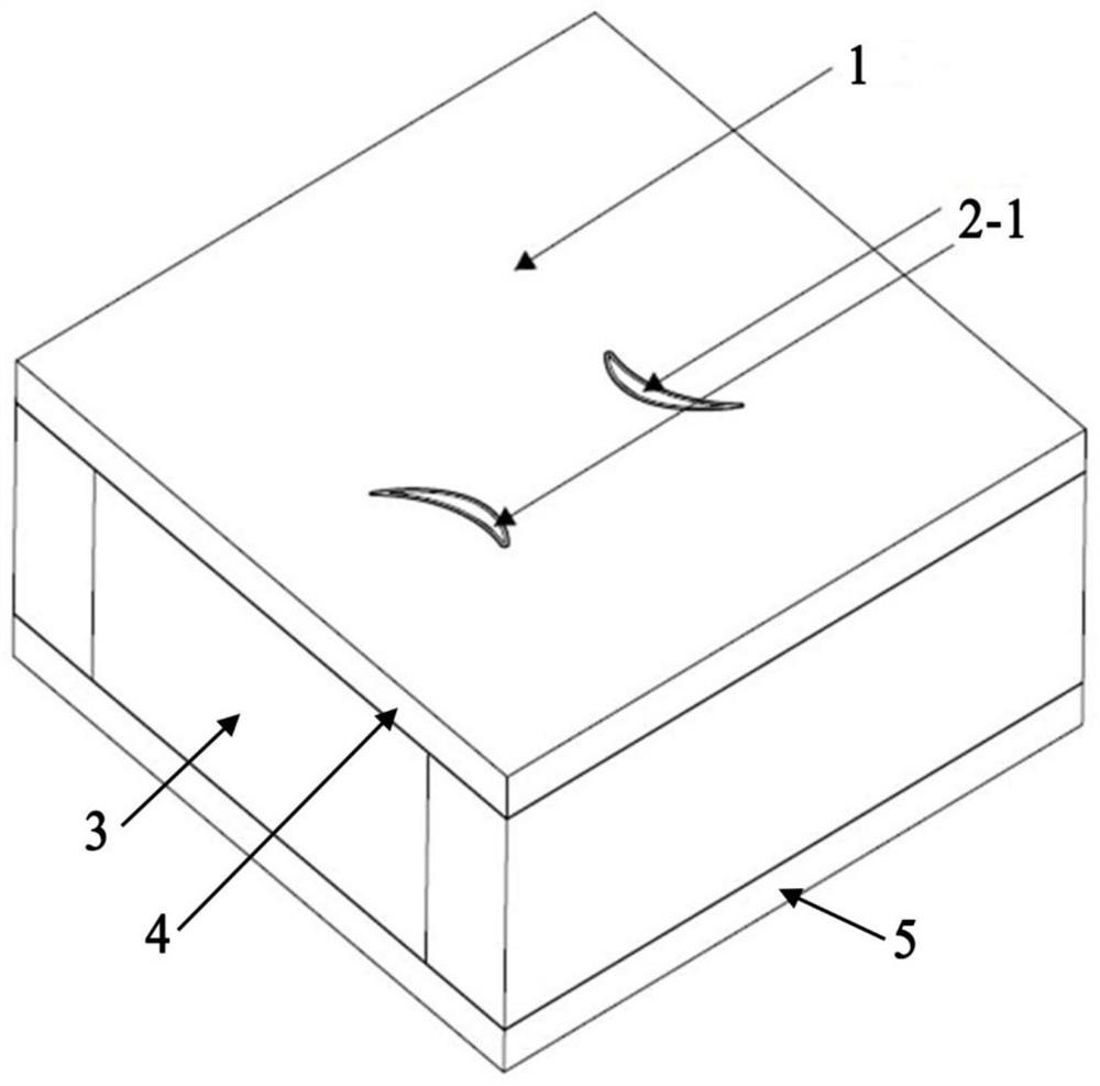
[0062] The side substrate 3 is a tooling side substrate with a size of 252mm×252mm×5mm, which is used to support and fix the upper substrate and substrate base. The shape is rectangular, and the size of the substrate depends on the size of the blade;

[0063] The upper substrate 4 has the same length, width and height as the substrate base, and a through hole with the same size and shape as the blade tip is provided at the blade installation position;

[0064] The size of the substrate base 5 is 252mm (length) × 10mm (width) × 125mm (height), and there are M8 threaded holes at the four corners of the substrate base, which can be connect...

example 2

[0082] Arcam A2X electron beam selective melting (EBM) equipment was used to repair the wear damage of the turbine blade tip of a certain type of engine DZ125 directionally solidified alloy. The specific steps are as follows:

[0083] S1. Tool design and blade clamping: Design a tool to assist blade positioning, clamping and electron beam melting (EBM) repair:

[0084] The side substrate 3 is a tooling side substrate with a size of 210mm×210mm×5mm, which is used to support and fix the upper substrate and substrate base. The shape is rectangular, and the size of the substrate depends on the size of the blade;

[0085] The upper substrate 4 has the same length, width and height as the substrate base, and a through hole with the same size and shape as the blade tip is provided at the blade installation position;

[0086] The size of the substrate base 5 is 210mm (length) × 10mm (width) × 125mm (height);

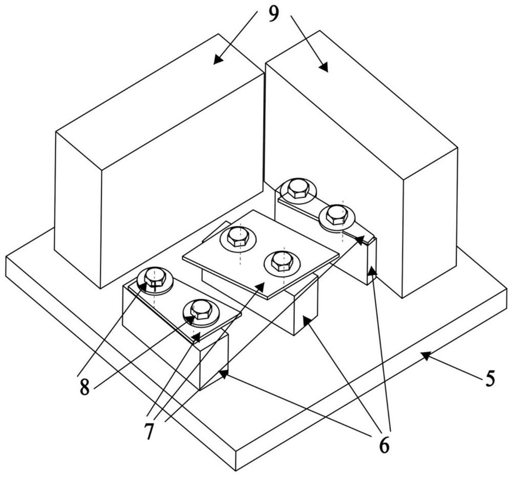
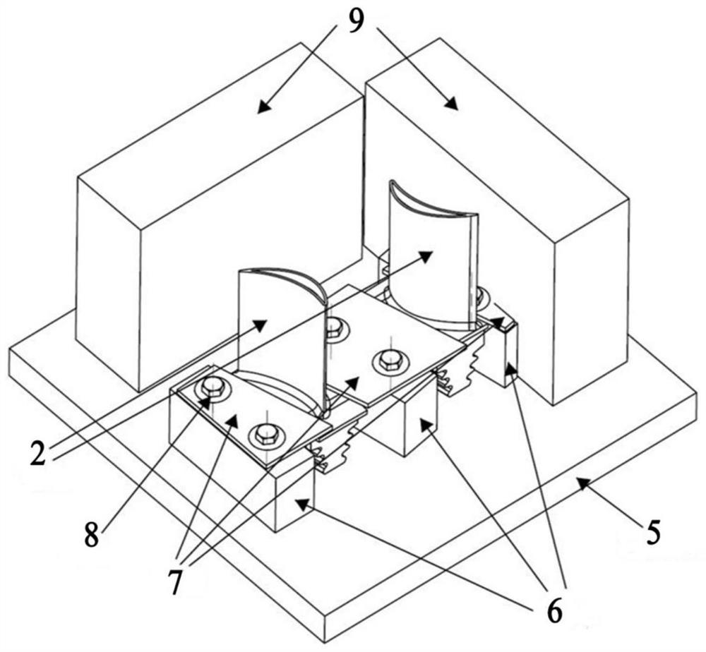
[0087] The size of the spacer 6 is 84mm (length) × 40mm (height), and the ...


PUM

PropertyMeasurementUnit
thicknessaaaaaaaaaa
sizeaaaaaaaaaa

Abstract

The invention belongs to the technical field of aero-engine hot end part repairing, and relates to a single crystal and directional solidification material turbine rotor blade tip repairing method andtool. According to the method, a laser selective melting or electron beam selective melting process is adopted for completing repairing, a blade can be placed in a forming area of laser selective melting or electron beam selective melting equipment through the tool and is formed at the blade tip, data are obtained through three-dimensional scanning for reverse modeling to obtain a model needing to be repaired and formed and related position information, the corresponding tool and blade clamping are designed, the structure and form of the tool are not limited, and the tool can be used for completing blade clamping, auxiliary positioning and position calibration; printing repairing forming is carried out after positioning calibration, and finally aftertreatment and detection are completed;and the positioning precision of blade repairing is well controlled, and the beneficial effects that heat input is small, grains are fine, the mechanical property is good, deformation is small, the surface roughness is good, the size precision is high, near-net forming does not need machining, and forming is rapid and efficient are achieved.

Description

technical field [0001] The invention belongs to the technical field of aero-engine maintenance, and relates to the repair of hot-end parts of the engine, in particular to a method and tooling for repairing a turbine rotor blade tip of a single crystal and directionally solidified material, and in particular to a turbine rotor blade made of a single crystal and directionally solidified material. Cutting-edge selective laser melting (SLM) and electron beam melting (EBM) restoration methods and tooling for restoration. Background technique [0002] The working environment of single crystal and directionally solidified material turbine rotor blades is high temperature and high pressure, and the tip part is easily damaged, which requires a lot of tip repair work. The traditional repair method is to use welding techniques such as laser welding to surfacing on the top of the blade, and then perform machining and grinding to remove excess material to complete the repair. This metho...

Claims


Application Information

Patent Timeline
Patent Type & Authority Applications(China)
IPC IPC(8): B22F3/105B22F3/24B22F7/06B33Y10/00B33Y30/00B33Y50/02B33Y80/00
CPCB22F3/24B22F3/003B22F7/062B33Y10/00B33Y30/00B33Y50/02B33Y80/00B22F2003/247B22F2007/068Y02P10/25
Inventor 张学军秦仁耀孙兵兵赵海生张强
Owner AVIC BEIJING INST OF AERONAUTICAL MATERIALS
Why Eureka
Try Eureka