
Carbide material for cutting devices and associated method of manufacture

A manufacturing method and carbide technology, applied in welding/cutting media/materials, manufacturing tools, additive manufacturing, etc., can solve the problem of limited hardness of tungsten carbide materials

Pending Publication Date: 2020-12-15
C4有限公司
View PDF10 Cites 3 Cited by
  • Summary
  • Abstract
  • Description
  • Claims
  • Application Information

AI Technical Summary

Problems solved by technology

Therefore, to date, the hardness achievable with tungsten carbide materials has been limited while still providing a material suitable for cutting

Method used


Image

  • Carbide material for cutting devices and associated method of manufacture
  • Carbide material for cutting devices and associated method of manufacture
  • Carbide material for cutting devices and associated method of manufacture

Examples


Embodiment Construction

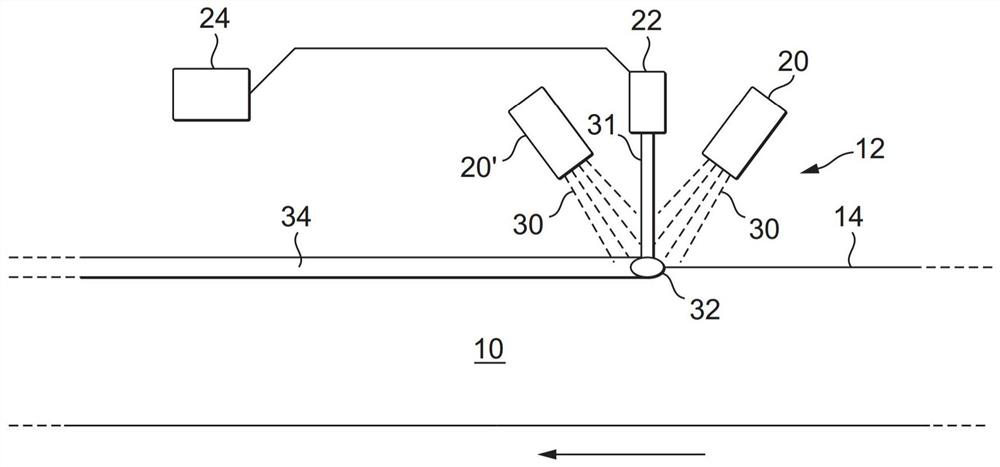
[0028] figure 1 Illustrated is a method of forming carbide material on a device such as a steel strip 10 that can be used as a blade in a tool such as a band saw, hack saw, jig saw, hole saw. The strip 10 may be formed with teeth if desired.

[0029] The strip 10 is moved relative to the station 12 to allow carbide material to form along the upper edge 14 of the strip 10 . Workstation 12 includes hoppers 20, 20' for supplying material in powder form and a high power energy source 22, typically a continuous wave fiber laser with a maximum power of 1 kW operating at 800 W, although the high power energy source 22 can apply a power range from 300W to 2kW. One or more computing devices 24 control the movement of the strip 10 relative to the workstation 12 and hoppers 20 , 20 ′, the supply of material from the hoppers 20 , 20 ′ and the output of the energy source 22 . Typically, the web 10 moves at a substrate traverse speed of 2 m / min, although the traverse speed may vary betwe...


PUM

PropertyMeasurementUnit
particle sizeaaaaaaaaaa

Abstract

The invention provides a carbide material for cutting devices and an associated method of manufacture. There is provided a carbide material (34) comprising Tungsten Carbide of 60 to 85 weight%, Titanium Carbides of 10 to 25 weight% and preferably a metal matrix of 0.5 to 20 weight% comprising Fe and optionally at least one or both of the metals Co or Ni. There is also provided a device comprisinga ferrous substrate and such a carbide material and a method of manufacturing a device, the method comprising mixing powders comprising Carbon, Tungsten and a scavenger material such as Titanium, placing the mixed powders proximal a ferrous substrate (10), impinging an energy source (31) onto the powdered materials to create a melt pool (32) formed of the powders and the material of the substrate,and allowing the melt pool to solidify to form a carbide material (34) substantially free from Iron Tungsten carbides of (W, Fe)6 C and (W, Fe)12 C type.

Description

technical field [0001] The present invention relates to a carbide material for deposition on an iron-containing base and to a method of manufacturing such a carbide material. Background technique [0002] For carbide materials used as coatings, high hardness values ​​are generally desired, and a common material is tungsten carbide in a metal matrix of cobalt or nickel because it provides Optimum hardness and toughness. [0003] Carbide materials can be deposited using an additive manufacturing process in which powder or wire material is melted or sintered by a high-energy, concentrated heat source such as a laser or electron beam. [0004] A known problem with the deposition of tungsten carbide onto ferrous substrates using additive manufacturing techniques is the formation of highly brittle iron-tungsten carbides (W, Fe) 6 C and (W, Fe) 12 C, it increases the brittleness of the material. Thus, until now, the material toughness achievable by depositing tungsten carbide o...

Claims


Application Information

Patent Timeline
Patent Type & Authority Applications(China)
IPC IPC(8): C22C29/08B22F7/08B22F3/105B22F5/00B33Y80/00B33Y10/00C04B35/56
CPCC22C29/08B22F7/08B22F5/00B33Y80/00B33Y10/00C04B35/5626B22F2005/001C04B2235/3843C04B2235/3847C04B2235/405C04B2235/3817B22F10/36B22F12/55B22F12/13B22F10/34B22F10/25B22F12/41B22F12/52B22F10/368C23C24/103C22C1/051C22C29/005Y02P10/25B23K26/342B23K35/32B33Y70/10C23C24/10B23B27/14C22C1/02
Inventor 龚俊彦A·克里斯安瑟尤P·塞维森科
Owner C4有限公司
Learn More