Eureka AIR delivers breakthrough ideas for toughest innovation challenges, trusted by R&D personnel around the world.

Refrigerant recovery device of ORC waste heat power generation turbo expander

A turbo-expander, waste heat power generation technology, applied in refrigerators, refrigeration components, refrigeration and liquefaction, etc., can solve the problems of high manufacturing cost, inaccessibility, expensive manufacturing equipment, etc., to reduce manufacturing difficulty and harsh requirements, The effect of avoiding waste of resources and facilitating assembly and use

Active Publication Date: 2020-12-15
联优机械(常熟)有限公司
View PDF6 Cites 0 Cited by
  • Summary
  • Abstract
  • Description
  • Claims
  • Application Information

AI Technical Summary

Problems solved by technology

[0003] In the prior art, pressure-resistant gearboxes and pressure-resistant oil systems are generally used, and the recovered oil and gas are usually returned directly to the system in the prior art, and then the oil is led back to the oil tank through layered backflow. The manufacturing requirements of the pressure gearbox and pressure-resistant oil system are relatively strict and the equipment used for manufacturing is also relatively expensive. Therefore, on the one hand, the manufacturing is difficult and costly, and on the other hand, the leakage prevention requirements are difficult or even impossible to meet the expectations of the industry; The treatment process of bringing recovered oil and gas directly back to the system and returning to the oil tank through stratified return flow is relatively complicated, and the effect of stratified treatment is also not enough to meet the requirements of the industry

Method used


Image

  • Refrigerant recovery device of ORC waste heat power generation turbo expander
  • Refrigerant recovery device of ORC waste heat power generation turbo expander

Examples


Embodiment 1

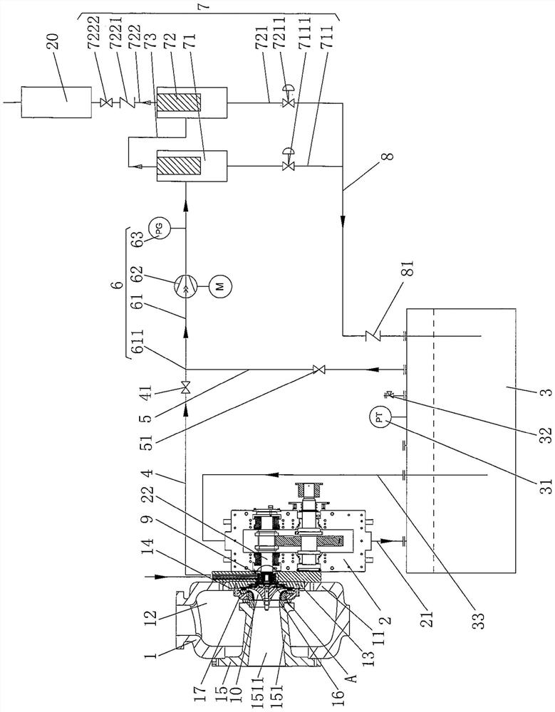
[0021] See figure 1 and figure 2, showing a volute 1, an impeller 10, a gear box 2 and an oil tank 3 of the structural system of the ORC waste heat power generation turbo expander, wherein the gear box 2 and the oil tank 3 belong to the auxiliary facilities of the turbo expander, A nozzle flow adjustment plate 13 is arranged at the center of the side of the volute bottom plate 11 of the volute 1 (that is, the "volute right side plate", the same below) facing the volute cavity 12, and is arranged on the left side of the volute 1. There is an air outlet ring 15, which is sealingly matched with the left side of the volute 1, and an air outlet ring 151 is formed at the center of the air outlet ring 15, and the right end of the air outlet pipe 151 extends into the volute cavity 12 , a sealing sleeve 16 and a nozzle pressure plate 17 are sequentially arranged on the right end of the air outlet pipe 151 of the air outlet ring, the left end of the seal sleeve 16 penetrates into the ...

Embodiment 2

[0037]Only change the aforementioned dry air to nitrogen. Since nitrogen is used as the sealed dry gas, the gas mixed with R134a and nitrogen is essentially a mixed gas of R134a and nitrogen. The gas mixed with oil gas and nitrogen is the mixed gas. It is essentially a mixture of oil gas and nitrogen. All the other are the same as the description to embodiment 1.


PUM


Abstract

A refrigerant recovery device of an ORC waste heat power generation turbo expander comprises a volute, an impeller, a gearbox and an oil tank, a nozzle flow adjusting plate is arranged on the side, facing a volute cavity, of a volute bottom plate, and a gas outlet ring is arranged on the left side of the volute bottom plate. The left end of the impeller stretches into a nozzle pressing plate cavity, the middle of the impeller corresponds to a gas duct, the right end of the impeller corresponds to an adjusting plate cavity, the gearbox is arranged on the right side of the volute bottom plate, the impeller is connected with an output shaft left shaft head, and the oil tank is arranged along with the gearbox. A dry gas sealing mechanism is arranged on the output shaft left shaft head. The refrigerant recovery device comprises a sealing gas recovery pipe, an oil-gas extraction pipe, an extraction mechanism, an oil-gas separation mechanism and an oil return pipe, one end of the sealing gasrecovery pipe is connected with the dry gas sealing mechanism, the other end of the sealing gas recovery pipe is connected with the extraction mechanism, one end of the oil-gas extraction pipe is connected with the oil tank, the other end of the oil-gas extraction pipe is connected with the extraction mechanism, and the extraction mechanism is connected with the oil-gas separation mechanism. The oil-gas separation mechanism is connected between a condensing device and one end of the oil return pipe, and the other end of the oil return pipe is connected with the oil tank. The manufacturing difficulty is reduced, and the sealing performance is good.

Description

technical field [0001] The invention belongs to the technical field of refrigerant recovery of a turbo expander, and in particular relates to a refrigerant recovery device of a turbo expander for ORC waste heat power generation. Background technique [0002] Turboexpander is an important equipment for energy recovery of waste heat and exhaust gas, engine waste heat recovery and utilization, differential pressure energy recovery and reuse, energy recovery and reuse of natural gas liquefaction and gasification, and comprehensive utilization of waste heat for gas co-generation. Among them, ORC waste heat power generation Turboexpander is generally favored by people because of its high recycling efficiency. [0003] In the prior art, pressure-resistant gearboxes and pressure-resistant oil systems are generally used, and the recovered oil and gas are usually returned directly to the system in the prior art, and then the oil is led back to the oil tank through layered backflow. T...

Claims


Application Information

Patent Timeline
Patent Type & Authority Applications(China)
IPC IPC(8): F25B45/00F25B43/02
CPCF25B43/02F25B45/00
Inventor 杨仁泓戈子文朱道祥杨雁钱沈
Owner 联优机械(常熟)有限公司
Why Eureka
Eureka Blog
Learn More