
Method of jointing target material and back plate

A bonding method and backplane technology, applied in welding equipment, non-electric welding equipment, metal processing equipment, etc., can solve the problems of easy generation of defects, unstable accumulated use time, and decreased adhesion rate, and achieve the effect of reducing bonding defects.

Inactive Publication Date: 2020-12-18
ZHEJIANG SAXUM SEMICON TECHNOLOGYCO LTD
View PDF9 Cites 1 Cited by
  • Summary
  • Abstract
  • Description
  • Claims
  • Application Information

AI Technical Summary

Problems solved by technology

By pressurization, BP expands to the outer circumference, and the central part forms a concave shape. In the outer peripheral part of TG after bonding, defects are easy to occur, and the adhesion rate will drop to about 90-96%, which is lower than the 98% required by diffusion bonding. question
In addition, due to the deformation, the thickness of the central part and the outer peripheral part of the TG will become different, which will also cause the problem of unstable cumulative use time.

Method used


Image

  • Method of jointing target material and back plate

Examples


Embodiment 1

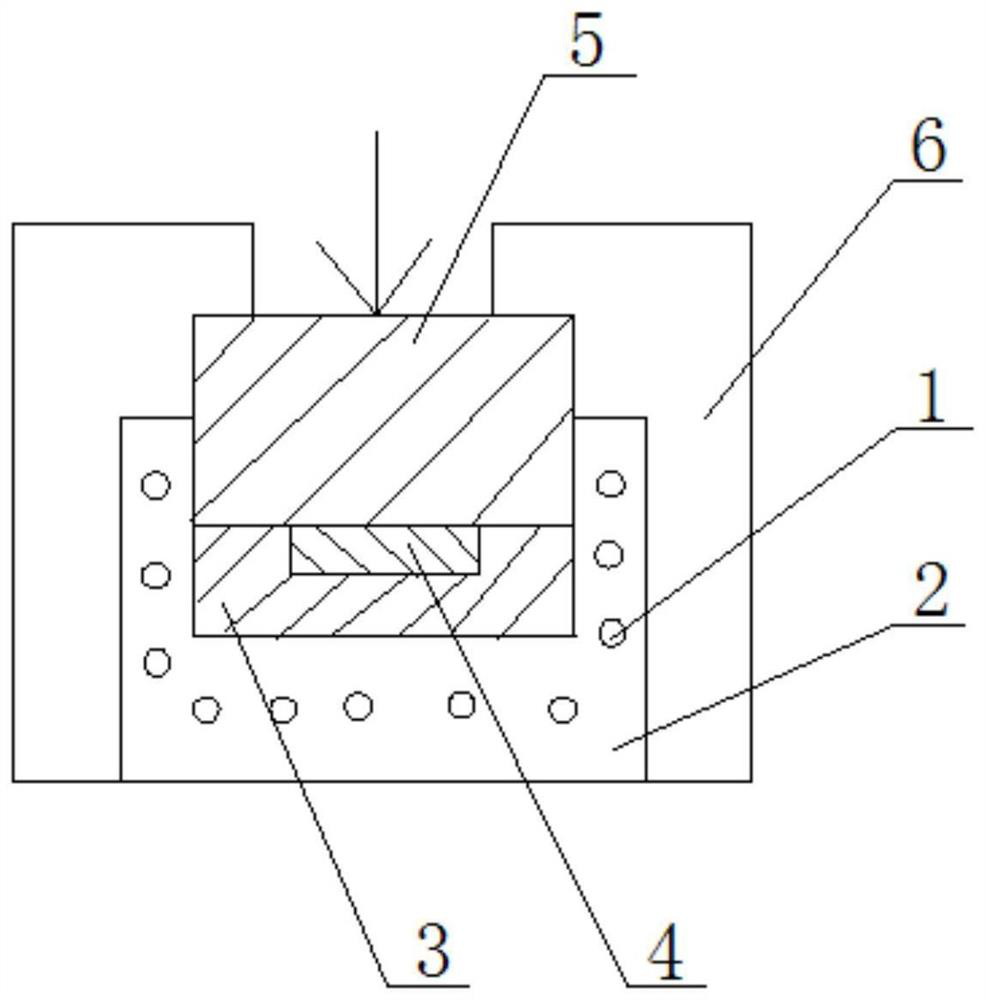
[0015] A bonding method for a target and a backplate, such as figure 1 The following steps are shown:

[0016] (1) Preheat the metal sheath 2 with the built-in heater 1 to 350°C as a whole, and then place it on the machine tool 6 of the hydraulic press;

[0017] (2) Just insert the back plate 3 into the groove of the metal sheath 2, place the target material 4 in the center of the upper surface of the back plate, and then place a briquetting block 5 having the same diameter as the back plate 3 on the upper surface of the target material 4;

[0018] (3) Heat the back plate 3 and the target material 4 to 400°C, and apply 8kg / mm ​​to the upper surface of the compact 5 2 After maintaining the temperature and pressure for 45 minutes, take out the back plate 3 and the target material 4, that is, complete the bonding of the back plate 3 and the target material 4, and check the defects of the bonding layer by an ultrasonic flaw detection machine, and more than 99% of the defects can ...

Embodiment 2

[0021] With above-mentioned embodiment 1, its difference is:

[0022] (1) Preheat the metal sheath 2 of the built-in heater 1 to 300°C as a whole, and then place it on the machine tool 6 of the hydraulic press;

[0023] (2) Just insert the back plate 3 into the groove of the metal sheath 2, place the target material 4 in the center of the upper surface of the back plate, and then place a briquetting block 5 having the same diameter as the back plate 3 on the upper surface of the target material 4;

[0024] (3) Heat the back plate 3 and the target 4 to 300°C, and apply 3kg / mm ​​to the upper surface of the compact 5 2 After keeping at this temperature and pressure for 120 minutes, take out the back plate 3 and the target material 4, that is, complete the bonding of the back plate 3 and the target material 4, and check the defects of the bonding layer by an ultrasonic flaw detection machine, and more than 99% of the defects can be obtained. the attachment rate.

Embodiment 3

[0026] With above-mentioned embodiment 1, its difference is:

[0027] (1) Preheat the metal sheath 2 of the built-in heater 1 to 400°C as a whole, and then place it on the machine tool 6 of the hydraulic press;

[0028] (2) Just insert the back plate 3 into the groove of the metal sheath 2, place the target material 4 in the center of the upper surface of the back plate, and then place a briquetting block 5 having the same diameter as the back plate 3 on the upper surface of the target material 4;

[0029] (3) Heat the back plate 3 and the target material 4 to 600°C, and apply 10kg / mm ​​to the upper surface of the compact 5 2 After maintaining the temperature and pressure for 30 minutes, take out the back plate 3 and the target material 4, that is, complete the bonding of the back plate 3 and the target material 4, and check the defects of the bonding layer by an ultrasonic flaw detection machine, and more than 99% of the defects can be obtained. the attachment rate.


PUM


Abstract

The invention discloses a method for jointing a target material and a back plate. The method is characterized by comprising the following steps: (1) a metal package sheath with a built-in heater is integrally preheated to 300-400 DEG C, and then is placed on a machine tool of a hydraulic machine; (2) a back plate is just inserted into a groove of the metal package sheath, the target material is placed in the center of the upper surface of the back plate, and then a pressing block with the same diameter as the back plate is placed on the upper surface of the target material; and (3) the back plate and the target material are heated to 300-600 DEG C, pressure of 3-10 kg / mm<2> is applied to the upper surface of the pressing block, 30-120 minutes are kept at the temperature and the pressure, and the back plate and the target material with the adhesion rate of 99% or above is taken out to finish jointing of the back plate and the target material, wherein the target material is aluminum, analuminum alloy, copper, a copper alloy, titanium, nickel or a nickel alloy, and the back plate is an aluminum alloy, copper or a copper alloy. The method has the advantages that the adhesion rate of the target material and the back plate is increased, the thickness of the target material is prevented from being changed, and jointing defects are reduced.

Description

technical field [0001] The invention relates to a bonding technology of a target, in particular to a bonding method of a target and a back plate. Background technique [0002] In the semiconductor industry, a target assembly is composed of a target that meets the sputtering performance and a back plate that is combined with the target and has a certain strength. The back plate can play a supporting role when the target assembly is assembled into the sputtering machine, and has the effect of conducting heat. In the manufacture of large-scale integrated circuits, aluminum targets are often used for physical vapor deposition (PVD) coating to form wiring layers. Magnetron sputtering is used for aluminum targets in the sputtering process, which usually has high strength, high thermal conductivity and high electrical conductivity. The copper material is used as the back plate material, but the aluminum target and the back plate material must be welded together to be processed int...

Claims


Application Information

Patent Timeline
IPC IPC(8): B23K20/00B23K20/02B23K20/24
CPCB23K20/002B23K20/02B23K20/023B23K20/24
Inventor 大岩一彦姚科科廣田二郎中村晃林智行山田浩
Owner ZHEJIANG SAXUM SEMICON TECHNOLOGYCO LTD
Learn More