
Steam generation system for solar photo-thermal power station and operation method of steam generation system

A generation system and operation method technology, which is applied in the steam generation method using heat carrier, solar thermal power generation, steam generation method, etc. Reliability and the effect of saving plant electricity

Pending Publication Date: 2020-12-18
ZHEJIANG SUPCON SOLAR TECHNOLOGY CO LTD
View PDF0 Cites 1 Cited by
  • Summary
  • Abstract
  • Description
  • Claims
  • Application Information

AI Technical Summary

Problems solved by technology

At present, for the steam generation system of subcritical and supercritical units, because the traditional natural circulation scheme is difficult to achieve efficient steam generation, the forced circulation scheme is adopted in the traditional design. This scheme needs to use a forced circulation pump as the steam drum and evaporation However, due to the use of the forced circulation pump, there are two problems: one of the problems is that the cost of the forced circulation pump is higher than that of the general water pump due to its high operating temperature and high operating pressure. The high expenditure affects the urgent need to reduce costs in the solar thermal power generation industry; the second problem is that since the forced circulation pump is a moving part, compared with the natural circulation scheme, it greatly increases the failure rate and operation risk of the system operation. From the current first batch The operation of the steam generation system of the solar thermal power generation demonstration project also proves the seriousness of this problem
[0005] In addition, due to the particularity of the molten salt heat exchanger, when the temperature of the water working medium in the molten salt heat exchanger is lower than the freezing point of the molten salt working medium, it will cause the molten salt to solidify and cause a production shutdown accident. Therefore, to improve the molten salt heat exchange The temperature of the water working medium at the inlet of the boiler is particularly important. The current solution is generally to add a group of heat exchangers in front of the molten salt heat exchanger to increase the temperature of the feed water. There may be a problem that the temperature of the feed water is lower than the freezing point of the molten salt working fluid
[0006] Therefore, it is necessary to find a safe solution that can not only properly solve the problem that natural circulation cannot meet the demand for steam generation, but also avoid the increase in cost and failure rate caused by the use of forced circulation pumps, and at the same time ensure that the inlet water of the molten salt heat exchanger The temperature of the working fluid is higher than the freezing point of the molten salt working fluid

Method used


Image

  • Steam generation system for solar photo-thermal power station and operation method of steam generation system
  • Steam generation system for solar photo-thermal power station and operation method of steam generation system

Examples


Embodiment 1

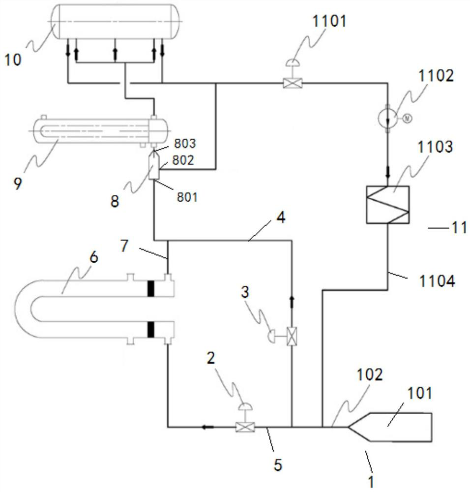
[0044] Please refer to figure 1 , a steam generation system for solar thermal power plants, the steam generation system provides water working fluid through the water supply unit 1; the steam generation system includes a preheater 6, a Venturi nozzle 8, an evaporator 9, a steam Package 10 and boot unit 11.

[0045] In this embodiment, the water supply unit 1 includes a water supply source 101 and a water supply pipeline 102 , and the water supply source 101 provides hydraulic fluid to the steam generation system through the water supply pipeline 102 . The water supply source 101 can also be connected to the water supply pipeline 102 through a regulating valve or a water supply pump, etc., in order to control the on-off of the water supply pipeline 102 . In order to facilitate water supply to the steam generation system from the water supply source 101 , in this embodiment, after the water supply source 101 pressurizes the hydraulic medium, water is supplied to the steam gener...

Embodiment 2

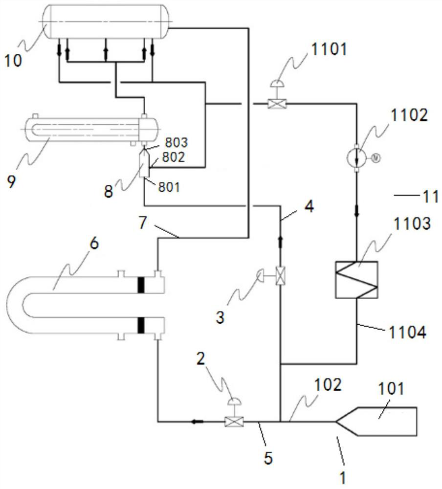
[0059]The difference between the steam generating system provided in this embodiment and the steam generating system provided in Embodiment 1 is that the preheater 6 in Embodiment 1 is connected to the nozzle inlet 801 of the Venturi nozzle 8 through its water outlet pipe 7, while in this embodiment Example preheater 6 is connected to the water supply pipe of steam drum 10 through its outlet pipe 7, please refer to figure 2 .

[0060] In this embodiment, when the steam generating system is started in a cold state, the start-up operation process is as follows:

[0061] First, open the water supply unit 1, close the water supply bypass regulating valve 3, open the water supply regulating valve 2 and start the circulation pump inlet switch valve 1101, and the pressurized hydraulic medium flows in the water supply pipeline 102, and the hydraulic engineering Substance flows into preheater 6, steam drum 10, Venturi nozzle 8, evaporator 9, steam drum 10, start circulation pump inle...


PUM


Abstract

The invention relates to a steam generation system for a solar photo-thermal power station and an operation method of the steam generation system. The steam generation system provides a water workingmedium through a water supply unit, and the steam generation system comprises a preheater, a venturi nozzle, an evaporator, a steam pocket and a starting unit. According to the steam generation systemand the operation method of the steam generation system, the feed water kinetic energy is utilized, meanwhile, the venturi nozzle principle is utilized, on one hand, the circulation volume of the steam-water medium between the evaporator and the steam pocket is promoted through the accelerated mixing function of the venturi nozzle, and the structure is between natural circulation and forced circulation; and on the other hand, when the feed water temperature is lower than the molten salt freezing point, the feed water can be mixed with steam water in a steam pocket downcomer through the venturi nozzle, and finally the temperature of the feed water entering the evaporator is increased. According to the steam generation system and the operation method of the steam generation system, the investment of a forced circulation pump is saved, the reliability of system operation is improved, and meanwhile the auxiliary power is saved.

Description

technical field [0001] The invention relates to the technical field of solar thermal power generation, in particular to a steam generation system and an operating method thereof for a solar thermal power station. Background technique [0002] There are various ways to utilize solar energy, including wind energy, tidal energy, photovoltaic power generation, solar thermal power generation and other technical categories. Solar thermal power generation can be divided into trough type, tower type, butterfly type and linear Fresnel according to the structure of concentrating mirror and heat collector. [0003] In order for solar thermal technology to stand out among many power generation technologies and ultimately achieve a major breakthrough in cost, at least two problems need to be solved, one is the reliability of the equipment, and the other is to optimize the system structure through process improvement. Reduce equipment investment. [0004] Whether it is a solar-thermal p...

Claims


Application Information

Patent Timeline
Patent Type & Authority Applications(China)
IPC IPC(8): F22B1/06F22B1/28F22B31/08F22B37/02F22B37/34F03G6/06
CPCF03G6/06F22B1/06F22B1/28F22B31/08F22B37/02F22B37/34Y02E10/46
Inventor 余志勇唐亚平毕文剑童郭凯
Owner ZHEJIANG SUPCON SOLAR TECHNOLOGY CO LTD
Learn More