25G optical module circuit integration device
A technology of circuit integration and optical modules, which is applied in the direction of circuit heating devices, circuits, printed circuits, etc., can solve the problems of dense connection of lower-end lines, bumps at solder joints, and people's injuries, so as to save materials, facilitate snapping, Effects that prevent damage
- Summary
- Abstract
- Description
- Claims
- Application Information
AI Technical Summary
Problems solved by technology
Method used
Image
Examples
Embodiment 1
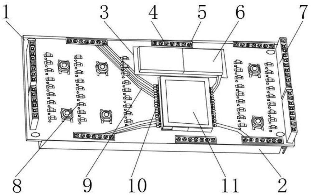
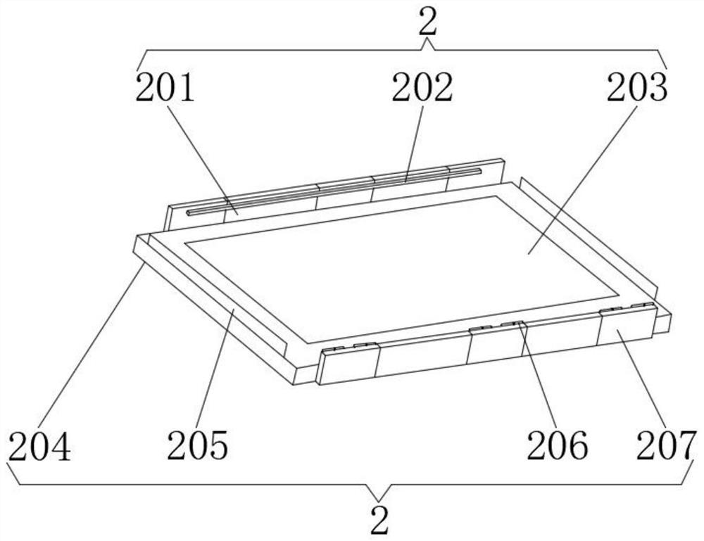
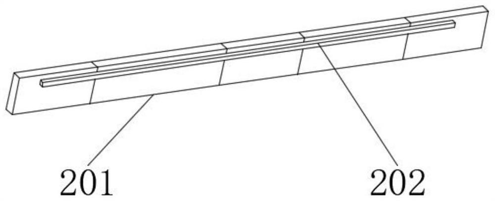
[0026] Embodiment 1, the positioning plate 201 is located on one side of the protection plate 204, the adjustment plate 207 is located on the other side of the protection plate 204, the hinge 206 is located on one side of the adjustment plate 207, the baffle plate 205 is located at both ends of the protection plate 204, and the drying layer 203 is positioned at the inside of protective plate 204, and positioning buckle 202 is positioned at the inboard of positioning plate 201, and between positioning plate 201 and positioning buckle 202, fixing block is arranged, and the inboard of positioning plate 201 is fixedly connected with one side of positioning buckle 202 by fixing block, A welding block is arranged between the protective plate 204, the positioning plate 201 and the adjusting plate 207, and the both sides of the protective plate 204 are fixedly connected with the inside of the positioning plate 201 and the adjusting plate 207 by the welding block, and one side of the adj...
Embodiment 2
[0027] In the second embodiment, the sealing and insulating pads 302 are located on both sides of the assembled board 301, the slider 303 is located inside the assembled board 301, the second pad 306 runs through the assembled board 301, the adjusting member 304 is located In the middle of the assembly plate 301, a chute is provided between the assembly plate 301 and the slider 303, the inside of both sides of the assembly plate 301 is movably connected with the outside of the slide block 303 through the chute, and the assembly plate 301 and the sealing insulating pad 302 are provided With superglue, the outer surface of the assembly board 301 is fixedly connected with the inner surface of the sealing insulating pad 302 through superglue. The assembly board 301 is provided with multiple groups, which are spliced on the inner side of the device main body 1, which can facilitate and better assemble the circuit board It can be replaced separately when there is a problem in weldi...
Embodiment 3
[0028]Embodiment 3, the integrated circuit includes a relay module, a power supply circuit, a central processing module, a display module, a light emitting module group, and a temperature detection module, and the power supply circuit is connected with a relay module, a central processing module, a display module, a light emitting module group, and a temperature detection module, The central processing module is connected with a display module, a light-emitting module group, and a temperature detection module. The temperature detection module is connected with a light-emitting module group. The power circuit supplies power to the central processing module, the display module, the light-emitting module group, and the temperature detection module. The relay module controls the power circuit switch. The output end of the central processing module is electrically connected to the input end of the display module and the light emitting module group, and the output end of the temperatu...
PUM
 Abstract
Description
Claims
Application Information
 - R&D
- Intellectual Property
- Life Sciences
- Materials
- Tech Scout
- Unparalleled Data Quality
- Higher Quality Content
- 60% Fewer Hallucinations
Browse by: Latest US Patents, China's latest patents, Technical Efficacy Thesaurus, Application Domain, Technology Topic, Popular Technical Reports.
© 2025 PatSnap. All rights reserved.Legal|Privacy policy|Modern Slavery Act Transparency Statement|Sitemap|About US| Contact US: help@patsnap.com


