Directional heat conduction material and preparation method and application thereof

A technology of directional heat conduction and heat conduction filler, applied in the direction of heat exchange materials, chemical instruments and methods, modification through conduction heat transfer, etc., can solve the problem of low degree of orientation, achieve high thermal conductivity, and improve axial thermal conductivity Effect

Active Publication Date: 2020-12-22
佛山(华南)新材料研究院
View PDF6 Cites 2 Cited by
  • Summary
  • Abstract
  • Description
  • Claims
  • Application Information

AI Technical Summary

Problems solved by technology

However, the degree of orientation that can be achieved by the existing orientation proce

Method used


Image

  • Directional heat conduction material and preparation method and application thereof

Examples


Embodiment 1

[0034] This embodiment provides an oriented thermally conductive material, which includes a polymer matrix and anisotropic thermally conductive fibers filled in the polymer matrix. The polymer matrix includes 40wt% spherical alumina and 60wt% silicone rubber, and the anisotropic thermally conductive fiber includes 5wt% carbon fiber and 95wt% paraffin. The volume fraction of the anisotropic heat-conducting fiber in the total volume of the oriented heat-conducting material is 30%. The anisotropic thermally conductive fibers are oriented within the polymer matrix, and the anisotropic thermally conductive fibers are oriented along the direction of their alignment.

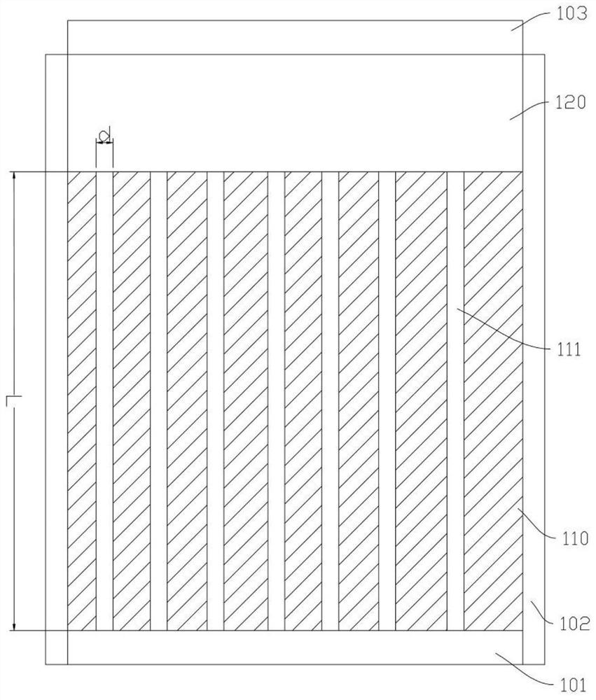
[0035] The mold used in the preparation process of the directional heat-conducting material is as follows:figure 1 shown, refer to figure 1 , is a side view of the mold of one embodiment of the present invention. The mold is a cylindrical structure, including a lower cover plate 101, and a side wall 102 is fixed alon...

Embodiment 2

[0045] This embodiment provides an oriented thermally conductive material, which includes: a polymer matrix and anisotropic thermally conductive fibers filled in the polymer matrix. The polymer matrix includes 50wt% spherical silica and 50wt% silicone rubber, and the anisotropic thermally conductive fiber includes 10wt% boron nitride and 90wt% silicone rubber. The volume fraction of the anisotropic heat-conducting fiber in the total volume of the oriented heat-conducting material is 30%. The anisotropic thermally conductive fibers are oriented within the polymer matrix, and the anisotropic thermally conductive fibers are oriented along the direction of their alignment.

[0046] The preparation method of the directional heat conducting material is as follows:

[0047] Step 1: Mix silicone rubber and boron nitride treated with coupling agent KH550 to form the first slurry, and silicone rubber and spherical silica treated with coupling agent KH550 to form the second slurry;

[...

Embodiment 3

[0064] This embodiment provides an electronic device, which includes a chip and a heat sink arranged in sequence, and a heat transfer adhesive is sandwiched between the chip and the heat sink, and the heat transfer adhesive includes the oriented thermally conductive material of Embodiment 1 . Using the directional heat-conducting material, the heat generated by the chip during operation can be quickly transferred to the heat sink for dissipation, effectively slowing down the temperature rise of the chip.


PUM


Abstract

The invention provides a directional heat conduction material as well as a preparation method and application thereof. The directional heat conduction material comprises a polymer matrix and anisotropic heat conduction fibers filled in the polymer matrix, the anisotropic heat conduction fibers are directionally arranged in the polymer matrix, and the anisotropic heat conduction fibers are orientedalong the directional arrangement direction. The directional heat conduction material at least has the following beneficial effects: the directional heat conduction material utilizes the anisotropicheat conduction fillers to form directionally arranged heat conduction fibers, and the heat conduction fibers are also oriented along the arrangement direction of the heat conduction fibers on the microscale, so that the heat conduction material can utilize the anisotropy of the fillers to the greatest extent; the orientation degree of the fillers is greatly improved, the high heat conduction performance can be achieved with the low proportion of the anisotropic heat conduction fillers, and the heat dissipation requirement brought by high-speed development of electronic devices is further met.

Description

technical field [0001] The invention relates to the technical field of heat management materials, in particular to an oriented heat conduction material and its preparation method and application. Background technique [0002] With the rapid development of electronic technology and the continuous rise of 5G communications, Internet of Things, new energy automotive electronics, smart wearable devices and other fields, the power density and integration of related electronic devices are increasing day by day. When the electronic device is working, a considerable part of the power loss is exported as heat, and the heat dissipation of the electronic device will directly lead to a rapid rise in the temperature of the electronic device and an increase in thermal stress, which will affect the reliability, safety and service life of the electronic device. pose a serious threat. This has also made people in the industry gradually realize that whether the thermal management material sy...

Claims


Application Information

Patent Timeline
IPC IPC(8): C08L83/04C08L91/06C08K9/06C08K7/06C08K7/18C08K7/04C09K5/14H05K7/20
CPCC08L83/04C09K5/14H05K7/2039C08L2205/025C08L2203/20C08L91/06C08K9/06C08K7/06C08K7/18C08K7/04
Inventor 崔巍孙琪祝渊迟克禹陈倩仪
Owner 佛山(华南)新材料研究院
Why Eureka
Try Eureka