
Combustion chamber system suitable for high-power-density diesel engine

A technology with high power density and combustion chamber, which is applied in the field of combustion chamber system, can solve the problems of increasing the working temperature of the piston, affecting the reliability of the engine, and limited effect, so as to promote the mixing effect, reduce the afterburning phenomenon, and weaken the effect of oil in the fire possible effect

Inactive Publication Date: 2020-12-22
HUAZHONG UNIV OF SCI & TECH
View PDF12 Cites 6 Cited by
  • Summary
  • Abstract
  • Description
  • Claims
  • Application Information

AI Technical Summary

Problems solved by technology

However, only the double-plump combustion chamber is used, and the time to split the oil-in-fire phenomenon is relatively limited. In addition, the structure of the double-plump combustion chamber needs to use the spray flame to hit the wall of the piston, and the complete oil-in-fire hits the boss of the combustion chamber. And complete the combustion of most of the fuel near the boss of the combustion chamber, which will further increase the working temperature of the piston and affect the reliability of the engine, and the further increase of the working temperature of the combustion chamber will make the oil-in-fire phenomenon more likely to occur, so only double The plume combustion chamber can't solve the oil-in-fire problem well
[0005] To sum up, in view of the "oil in fire" phenomenon existing in high-power diesel engines such as special power plants, the current combustion chamber technology is difficult to completely solve, and there is an urgent need for research and design in this field to obtain a technology that can significantly improve the "oil in fire" phenomenon , so as to improve the overall performance of high-liter diesel engines such as special power units

Method used


Image

  • Combustion chamber system suitable for high-power-density diesel engine
  • Combustion chamber system suitable for high-power-density diesel engine
  • Combustion chamber system suitable for high-power-density diesel engine

Examples


Embodiment Construction

[0026] In order to make the object, technical solution and advantages of the present invention clearer, the present invention will be further described in detail below in conjunction with the accompanying drawings and embodiments. It should be understood that the specific embodiments described here are only used to explain the present invention, not to limit the present invention. In addition, the technical features involved in the various embodiments of the present invention described below can be combined with each other as long as they do not constitute a conflict with each other.

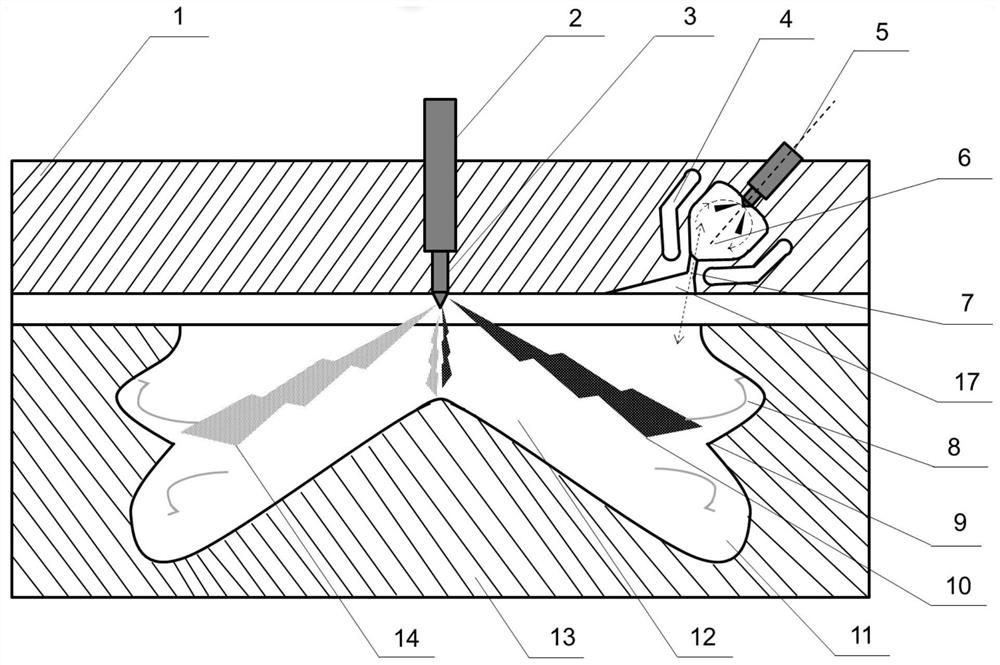
[0027]Embodiments of the present invention provide a main and auxiliary dual combustion chamber system for a high power density diesel engine, wherein, for the main combustion chamber, the oil-in-fire phenomenon is suppressed in the following manner: 1) utilizing the auxiliary combustion chamber in the dual combustion chamber system The high-temperature and high-pressure gas produced is ejected ...


PUM


Abstract

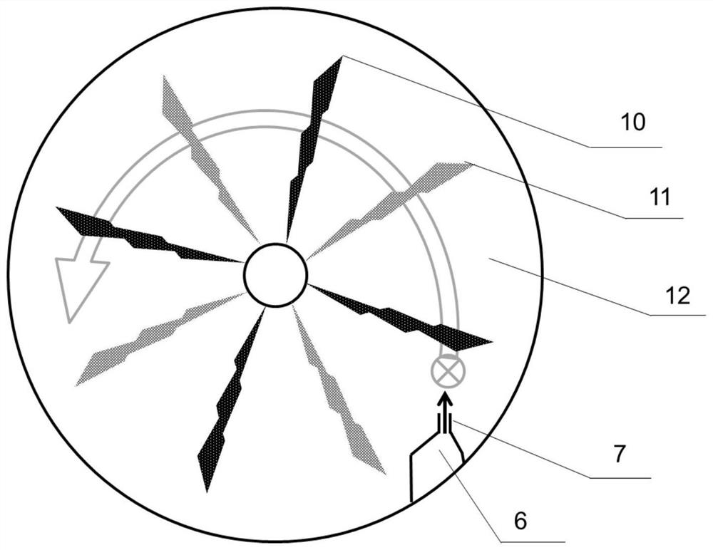
The invention belongs to the related technical field of diesel engines, and discloses a combustion chamber system suitable for a high-power-density diesel engine. The combustion chamber system comprises a main combustion chamber and an auxiliary combustion chamber, wherein a fuel oil mist beam of a fuel injector in the main combustion chamber points to a protrusion of the main combustion chamber,collides with the protrusion and is divided into an upward plume and a downward plume, and the tendency of forming oil-in-fire in the later period of combustion is weakened; high-temperature and high-pressure gas combusted in the auxiliary combustion chamber is sprayed out through a throat opening and comprises a horizontal component and a vertical component, the horizontal component disturbs thespraying direction of the fuel oil mist beam in the main combustion chamber, the oil-in-fire phenomenon in the early combustion stage is broken, and the vertical component pushes a piston to do work downwards; and air entering the auxiliary combustion chamber through the throat opening forms a rotational flow in the auxiliary combustion chamber, complete combustion of fuel oil in the auxiliary combustion chamber is promoted, and the inhibition effect on the oil-in-fire phenomenon is improved. According to the combustion chamber system, the oil-in-fire phenomenon existing in the high-power-per-liter diesel engine is solved, the combustion efficiency of an internal combustion engine is improved, and the practicability is very high.

Description

technical field [0001] The invention belongs to the technical field related to diesel engines, and more specifically relates to a combustion chamber system suitable for high power density diesel engines. Background technique [0002] The combustion process of an internal combustion engine can be summarized into the following steps: the intake valve opens, the piston moves downward to inhale air; the intake valve closes, the piston moves upward to compress the air to form a high-temperature and high-pressure environment; near the top dead center of the piston, fuel is injected into the combustion chamber, and after Atomization, evaporation, mixing, etc. form a partially combustible mixture, which is then naturally ignited in a high-temperature and high-pressure environment; the fuel burns and releases heat, and the gas expands rapidly to push the piston down and do work to the outside; then the exhaust valve opens, and the piston moves upward to release the burned exhaust gas ...

Claims


Application Information

Patent Timeline
IPC IPC(8): F02B23/06F02B23/02F02F1/24F02M29/00
CPCF02B23/02F02B23/06F02B23/0669F02F1/24F02M29/00Y02T10/12
Inventor 王兆文张新华吴慧珉成晓北向林
Owner HUAZHONG UNIV OF SCI & TECH
Learn More