Sectional type guide plate, flue gas on-line adjusting and flow equalizing device and flow equalizing method

A deflector and segmented technology, which is applied in the field of SCR denitrification in coal-fired power plants, can solve problems such as difficult adjustment and unsatisfactory flow field adjustment, and achieve the effect of timely and accurate flow field adjustment and change of roughness

Inactive Publication Date: 2020-12-25
SHANDONG UNIV +1
View PDF9 Cites 5 Cited by
  • Summary
  • Abstract
  • Description
  • Claims
  • Application Information

AI Technical Summary

Problems solved by technology

[0006] In order to solve the technical problems existing in the prior art, the object of the present invention is to provide a segmented deflector, a flue gas online adjustment flow equalization device and a flow equalization method. According to real-time measurement data, combined with numerical simulation calculation, Targeted adjustment of part of the deflector can realize the precise adjustment of the entire flow field of the flue, avoiding the traditional fixed deflector that cannot meet the needs of flow field adjustment when the load changes and the traditional full-section deflector. When adjusting the flow field, the overall flow field changes and it is difficult to adjust the problem

Method used


Image

  • Sectional type guide plate, flue gas on-line adjusting and flow equalizing device and flow equalizing method
  • Sectional type guide plate, flue gas on-line adjusting and flow equalizing device and flow equalizing method
  • Sectional type guide plate, flue gas on-line adjusting and flow equalizing device and flow equalizing method

Examples


Embodiment 1

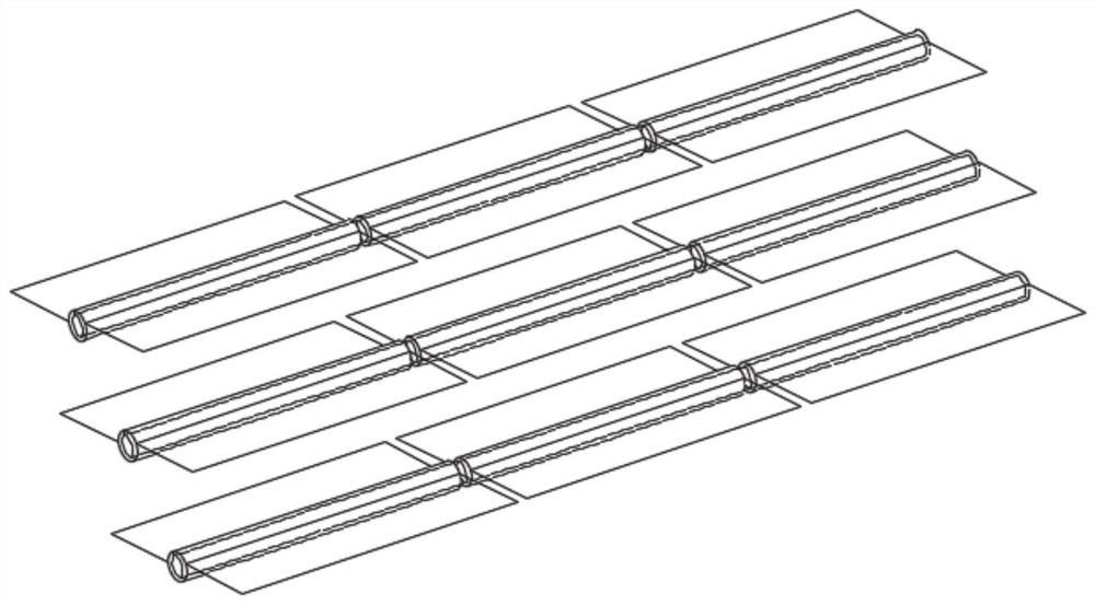
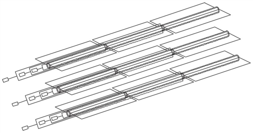
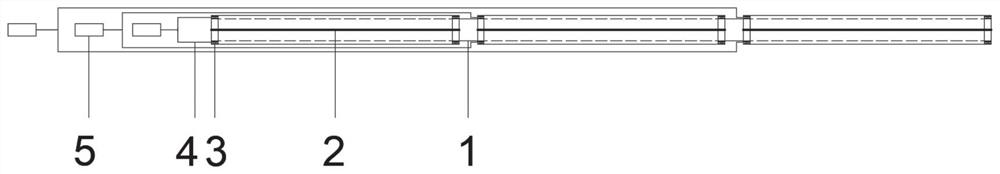
[0049] figure 1 It is a schematic structural diagram of a typical embodiment of the segmented deflector of the present invention. figure 2 It is a perspective structural diagram of a segmented deflector according to an embodiment of the present invention. On the basis of the segmented deflector, a power part is added, wherein the power part is composed of a motor and a rotating shaft. The overall design consists of a main shaft 1, a deflector 2, a bearing 3, a rotating shaft 4 and a motor 5 with an angle sensor. The control device of each deflector adopts a multi-axis design. Each flow deflector is controlled by an independent motor, and the motor and the flow deflector are connected by a rotating shaft. The motor can act after receiving the signal from the calculation and control device, thereby driving the flow deflector to rotate.

[0050] Such as Figure 4 As shown, in order to adjust the uniformity of the flue gas flow field at the outlet of the dust collector, accordi...

Embodiment 2

[0053] The layout of the first-stage deflector unit 11 is determined by the numerical simulation results, such as Figure 5 From the shown ammonia injection grille to the height of 1 / 3 of the top section, three sections of deflectors are arranged in sequence along the width direction of the flue at equal intervals, and each section of the deflector is equipped with three pieces of deflectors. The rotation angle of each deflector around the axis is -15° to 15° (the initial installation angle is defined as 0°). The distance between the baffles and between the baffles and the flue is greater than L1sin15° (L1 is the length of the first-stage baffles).

[0054] When the second stage deflector unit 12 is installed, it is arranged in such as Figure 5 At the cross-section of the flue outlet shown, three sections of deflectors are arranged equidistantly along the height direction of the flue. The deflectors are installed parallel to the inclined cover of the denitrification system, ...


PUM


Abstract

The invention discloses a sectional type flow guide plate, a flue gas on-line adjustment flow equalizing device and a flow equalizing method, and the sectional type flow guide plate comprises a main shaft which is a fixed shaft and is used for supporting and fixing; at least threeflow deflectors, wherein the flow deflectors are movably installed on the main shaft through respective rotating shafts; a bearing arranged between the rotating shaft and the main shaft, wherein the rotating shaft can smoothly rotate relative to the main shaft; and the motors corresponding to the flow deflectors in number, arranged at the end part of the main shaft and respectively connected with the rotating shaft of each flow deflector. According to real-time measurement data, part of the flow guide plates are adjusted in a targeted mode through the calculation and control device, partition accurate adjustment of a flue full flow field can be achieved, and the problems that a traditional fixed flow guide plate is subjected to load changes, the needs of flow field adjustment cannot be met, and the traditional whole-section flow guide plate when adjusting the flow field causes the overall flow field to change and is difficult to adjust are solved.

Description

technical field [0001] The invention relates to the technical field of SCR denitrification in a coal-fired power plant, in particular to a segmented deflector, a flue gas online regulating flow equalization device and a flow equalization method. Background technique [0002] The information disclosed in this background section is only intended to increase the understanding of the general background of the present invention, and is not necessarily taken as an acknowledgment or any form of suggestion that the information constitutes the prior art already known to those skilled in the art. [0003] In order to meet the requirements of ultra-low emissions, most coal-fired power plants choose to use selective catalytic reduction (SCR) denitrification technology. temperature range, NH 3 It selectively reacts with NOx in the flue gas under the catalytic action of the catalyst to form N 2 And water, so as to achieve the purpose of removing NOx in the flue gas. [0004] Since the ...

Claims


Application Information

Patent Timeline
Patent Type & Authority Applications(China)
IPC IPC(8): B01D53/86B01D53/56
CPCB01D53/8631B01D2258/0283
Inventor 孙奉仲郑鹏
Owner SHANDONG UNIV
Why Eureka
Try Eureka