Multifunctional unmanned aerial vehicle and using method thereof

A drone and multi-functional technology, applied in the field of drones, can solve the problems of affecting flight performance, large buoy area, and strong wind influence, etc., to achieve the effect of improving firmness, ensuring stability, and firm fixing effect

Inactive Publication Date: 2020-12-25
衡阳云雁航空科技有限公司
View PDF1 Cites 3 Cited by
  • Summary
  • Abstract
  • Description
  • Claims
  • Application Information

AI Technical Summary

Problems solved by technology

The UAV in the above-mentioned patent has the following disadvantages: Although the problem of water surface stability is solved to a certain extent, during the flight, due to the large area of ​​the buoy, it is greatly affected by the wind, which affects the flight performance.

Method used


Image

  • Multifunctional unmanned aerial vehicle and using method thereof
  • Multifunctional unmanned aerial vehicle and using method thereof
  • Multifunctional unmanned aerial vehicle and using method thereof

Examples


Embodiment 1

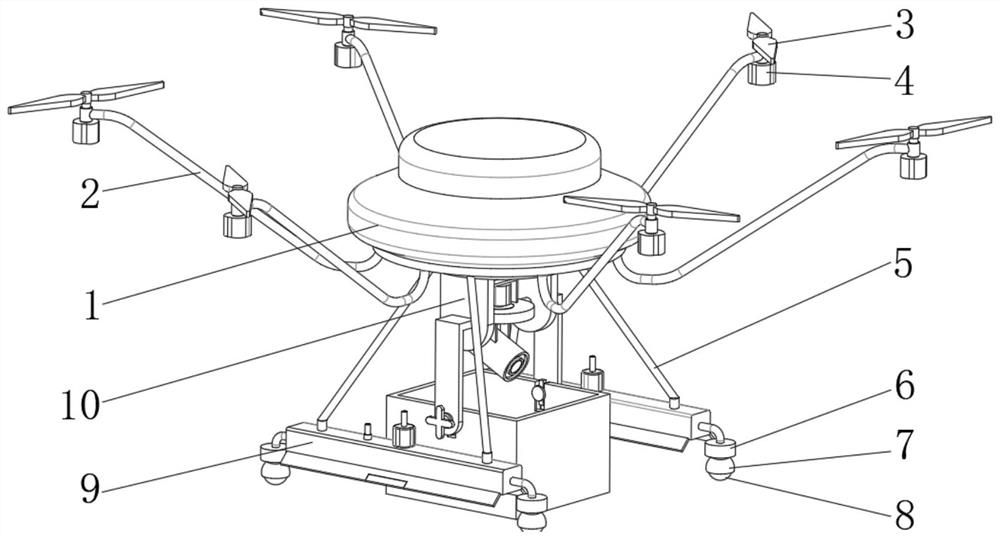
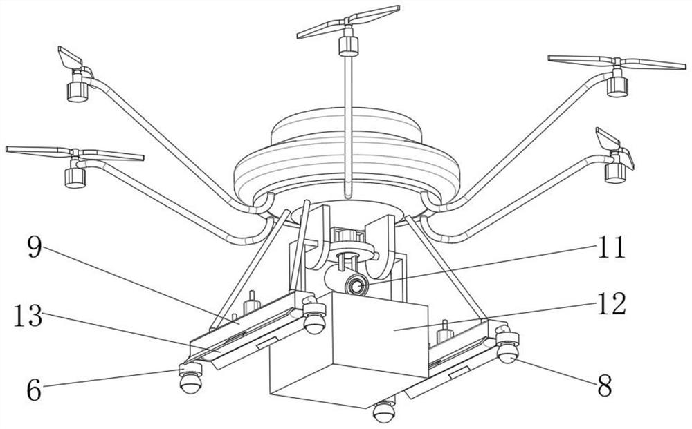
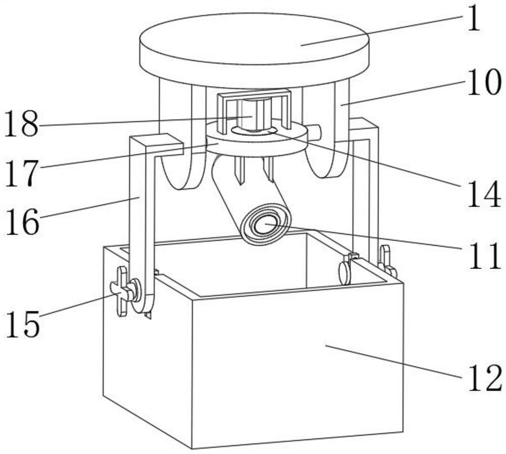
[0044] A multifunctional drone, such as Figure 1-5As shown, it includes a body 1 and a first motor 4, and the peripheral outer wall of the body 1 is respectively equipped with uniformly distributed wings 3 through assembly rods 2, and the wings 3 are respectively connected to the output ends of the first motor 4 through shaft rotation; The number of wings 3 is an even number of more than six; the body 1 is provided with a camera mechanism, and the outer walls on both sides of the bottom of the body 1 are respectively equipped with two symmetrical airbag chambers 9 through four connecting rods 5. 9 inner walls are embedded with an air bag 13, and the outer wall of the top of the air bag chamber 9 is fixed with a small air pump 20 by screws. Valve 19, the body 1 is provided with a control unit, the exhaust valve 19 and the small air pump 20 are electrically connected to the control unit; the outer walls on both sides of the airbag chamber 9 are fixed with a buffer seat 6 by scr...

Embodiment 2

[0052] A method of using a multifunctional drone, such as Figure 1-5 As shown, the control method of the airbag 13 and the loading and unloading method of the accommodating box 12 are included; the control method of the airbag 13 includes the following steps:

[0053] S1: Send a signal to the control unit in body 1 through remote control;

[0054] S2: the control unit receives the signal to control the small air pump 20 to work;

[0055] S3: the small air pump 20 works to inject gas into the air bag 13;

[0056] S4: The airbag 13 expands to expose the bottom of the airbag chamber 9 after the baffle 23 is opened, and provides enough buoyancy for the body 1 to float on the water surface;

[0057] S5: After the operation is finished, the control unit controls the exhaust valve 19 to exhaust;

[0058] S6: the airbag 13 shrinks back into the airbag chamber 9 , and the baffle 23 is reset under the action of the first magnet block 22 .

[0059] In order to realize the function o...


PUM


Abstract

The invention discloses a multifunctional unmanned aerial vehicle and a using method thereof, and relates to the technical field of unmanned aerial vehicles. The flight performance and the landing stability are balanced. The multifunctional unmanned aerial vehicle comprises a vehicle body and a first motor, an even number of more than six wings which are evenly distributed are installed on the outer wall of the circumference of the vehicle body through assembly rods, and the wings are correspondingly and rotationally connected to the output end of the first motor through shafts. The using method of the unmanned aerial vehicle comprises the steps of air bag controlling and containing box assembling and disassembling. The air bag controlling comprises the following step of sending a signal to a control unit in the vehicle body through remote control. By arranging air bags, a small air pump, the exhaust valve and other structures, enough buoyancy floating on the water surface is providedfor the vehicle body, and the stability of the vehicle body is guaranteed to a large extent; and by arranging the structures such as rolling balls, rolling ball seats and springs, rolling four-point floating type supporting can be achieved, and the vehicle body can reliably rise and fall on planes such as land.

Description

technical field [0001] The invention relates to the technical field of unmanned aerial vehicles, in particular to a multifunctional unmanned aerial vehicle and a method for using the same. Background technique [0002] UAV is a kind of aircraft controlled by radio remote control equipment and self-contained program control device. It is mostly used in aerial photography, agriculture, plant protection and other fields. , general drones can no longer meet the operating requirements of a specific environment. The amphibious drones that have been developed so far meet people's needs to a certain extent, but the stability of landing and after landing is not good, which affects the shooting effect. etc.; some amphibious UAVs use large buoys and other structures. Although the problem of water surface stability is solved to a certain extent, during the flight, due to the large area of ​​the buoys, they are greatly affected by the wind and affect flight performance. Therefore, the tr...

Claims


Application Information

Patent Timeline
Patent Type & Authority Applications(China)
IPC IPC(8): B64C27/08B64D47/08B64D9/00B64C25/36B64C25/56B64C25/62
CPCB64C27/08B64D47/08B64D9/00B64C25/36B64C25/56B64C25/62B64U10/10B64U2101/30B64U2101/60
Inventor 王国初李兆志王江王治玺
Owner 衡阳云雁航空科技有限公司
Why Eureka
Try Eureka