Grain drying and cooling cylinder

A grain drying and cooling cylinder technology, applied in the agricultural field, can solve the problem of uneven drying and achieve the effect of uniform drying and fast cooling

Inactive Publication Date: 2020-12-25
ANHUI GUFENG MECHANICAL TECH CO LTD
View PDF10 Cites 0 Cited by
  • Summary
  • Abstract
  • Description
  • Claims
  • Application Information

AI Technical Summary

Problems solved by technology

[0003] Since the freshly harvested grains contain a lot of water, it is necessary to reduce the moisture content in the grains during storage to prevent them from rotting and germination. When the existing drying device is drying, the grains will be stacked together, resulting in uneven drying. Therefore, in view of the above status quo, it is urgent to develop a grain drying and cooling cylinder with uniform drying and fast cooling speed, so as to overcome the deficiencies in the current practical application and meet the current needs.

Method used


Image

  • Grain drying and cooling cylinder
  • Grain drying and cooling cylinder
  • Grain drying and cooling cylinder

Examples


Embodiment 1

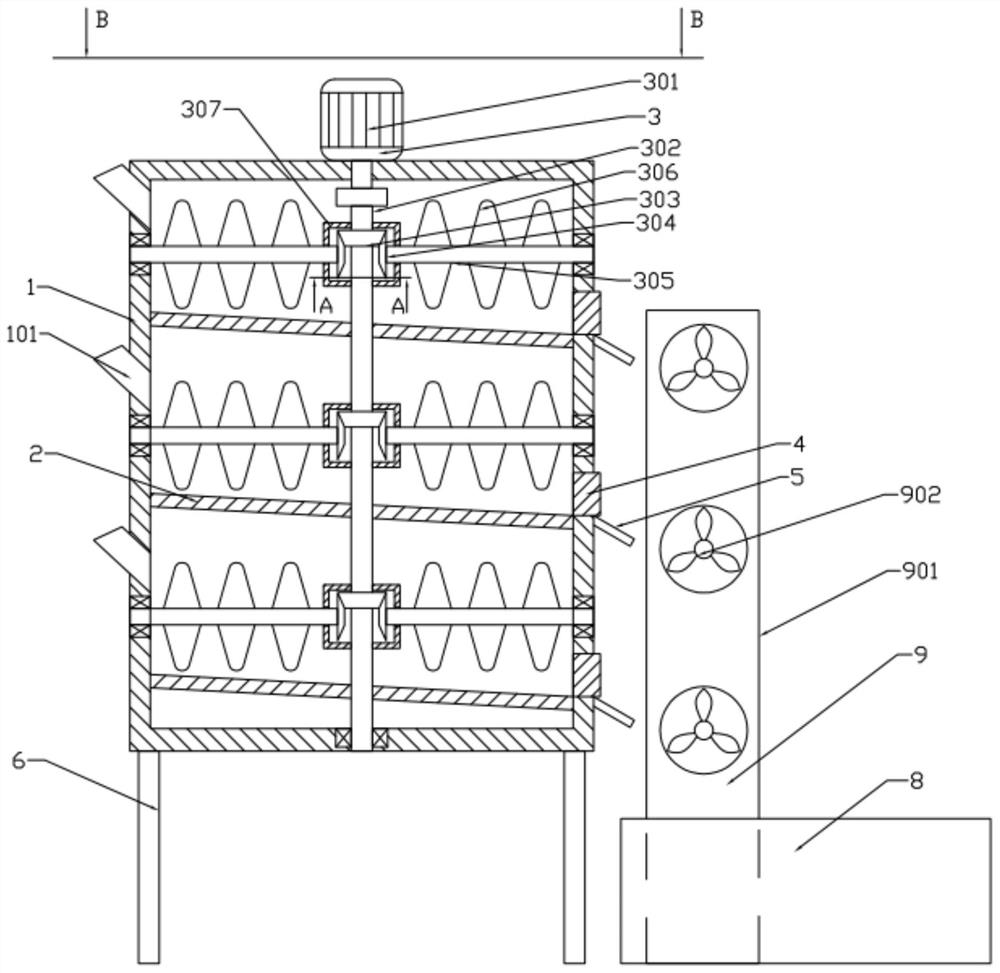
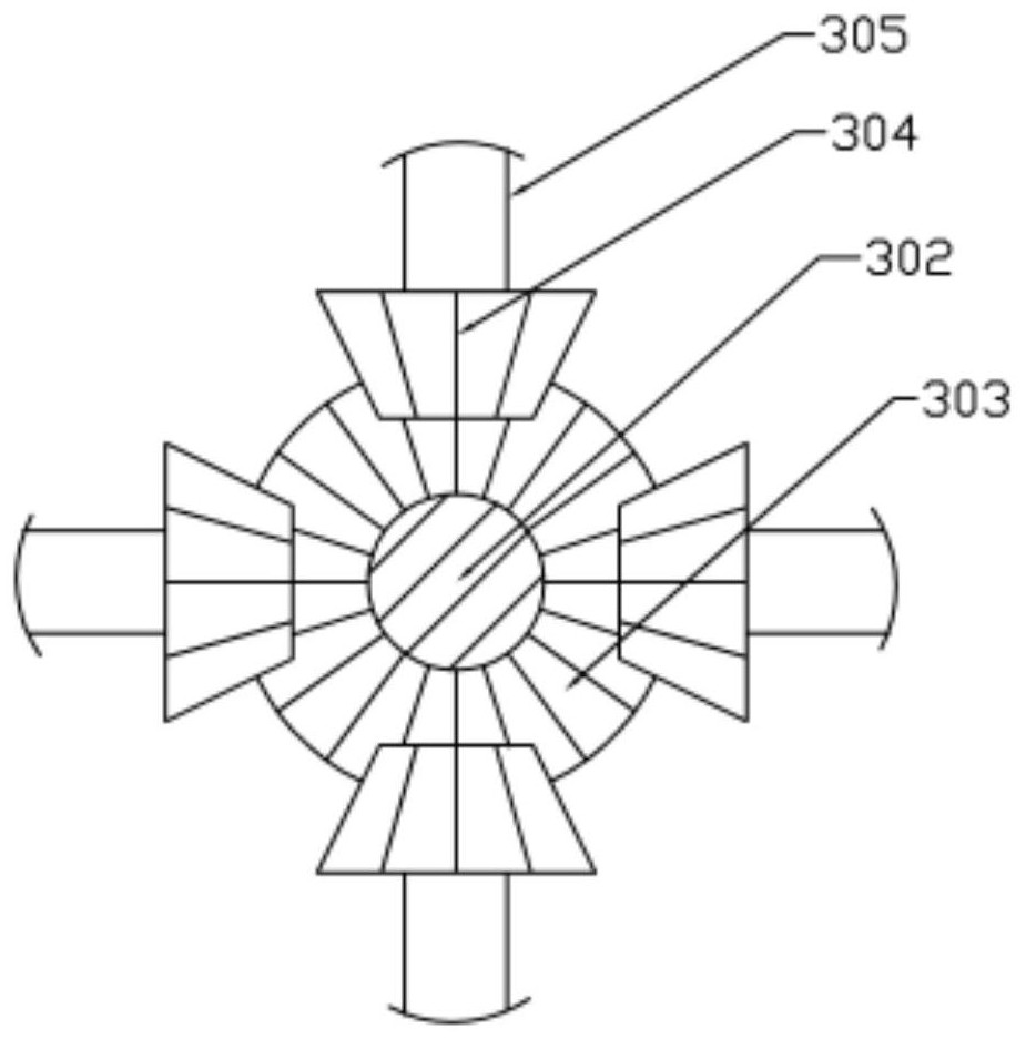
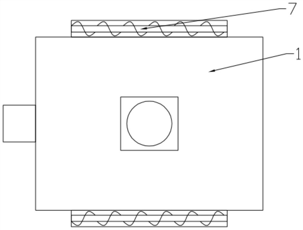
[0020] see Figure 1~3 , in an embodiment of the present invention, a grain drying and cooling cylinder includes a drying box 1, and three partition plates 2 are installed in the drying box 1, and the top of the three partition plates 2 is placed in the drying box. The left side of 1 is respectively provided with a feeding hopper 101, and the top of the drying box 1 is equipped with a turning mechanism 3 extending to the inside, and the turning mechanism 3 includes: a servo motor 301, a transmission shaft 302, a first cone Gear 303, second bevel gear 304, turning shaft 305, blade 306 and protective box 307, described servomotor 301 is installed on the top of drying box 1, the output shaft of described servomotor 301 passes shaft coupling and transmission shaft 302 Connected, three first bevel gears 303 are evenly distributed on the transmission shaft 302, and four second bevel gears 304 are installed on the underside of each first bevel gear 303 to rotate with it. The second ...

Embodiment 2

[0022] see figure 1 , in the embodiment of the present invention, the angle between the partition plate 2 and the horizontal plane is 5°.

[0023] When the grain drying and cooling cylinder is in use, the grain is respectively added into the drying box 1 from the three feeding hoppers 101, the heater 7 is started, the drive shaft 302 is driven by the servo motor 301 to rotate, and the drive shaft 302 is rotated to drive the first A bevel gear 303 rotates, rotates through the first bevel gear 303 and drives the second bevel gear 304 to rotate, rotates through the second bevel gear 304 and drives the turning shaft 305 to rotate, turns the blade 306 to rotate through the turning shaft 305, and rotates the grain through the blade 306. Stirring is conducive to more uniform drying; when the drying is over, the baffle plate 4 is removed, and the grain slides from the feeding chute 6 into the cooling box 8. Blow to cool.


PUM


Abstract

The invention discloses a grain drying and cooling cylinder which comprises a drying box. Three partition plates are installed in the drying box; a turning mechanism extending into the drying box is installed at the top of the drying box; baffles are installed at the positions, at the right ends of the three partition plates, of the drying box respectively; discharging sliding grooves are formed in the positions, below the three baffles, of the drying box respectively; heaters are respectively arranged on two sides of the drying box; and the right side of the drying box is provided with a cooling box and a cooling device on the ground. The grain drying and cooling cylinder provided by the invention is uniform in drying and high in cooling speed.

Description

technical field [0001] The invention relates to the field of agricultural technology, in particular to a grain drying and cooling cylinder. Background technique [0002] Cereals do not only refer to the seeds of gramineous plants. To be precise, they can be roughly divided into three categories in my country. Cereals: including rice (indica rice, japonica rice, and rice), wheat (wheat, barley, oats, rye) , corn, sorghum, millet, millet, yellow rice, buckwheat, etc.; legumes: including soybeans, broad beans, peas, mung beans, red beans, kidney beans, etc.; potatoes: including sweet potatoes, also known as sweet potatoes or white potatoes, potatoes, yams, taro , cassava, etc. [0003] Since the freshly harvested grains contain a lot of water, it is necessary to reduce the moisture content in the grains during storage to prevent them from rotting and germination. When the existing drying device is drying, the grains will be stacked together, resulting in uneven drying. Therefor...

Claims


Application Information

Patent Timeline
IPC IPC(8): F26B11/16F26B23/00F26B25/00F26B25/02F26B25/04F25D1/00A23B9/08
CPCA23B9/08F25D1/00F26B11/16F26B23/00F26B25/00F26B25/002F26B25/02F26B25/04F26B2200/06Y02A40/963
Inventor 刘吉勇许存伍
Owner ANHUI GUFENG MECHANICAL TECH CO LTD
Why Eureka
Try Eureka