
Clock dynamic switching circuit

A technology for switching circuits and clocks, applied in electrical components, pulse processing, generating/distributing signals, etc., can solve problems such as circuit abnormalities

Pending Publication Date: 2020-12-25
深圳市鹏芯数据技术有限公司
View PDF0 Cites 3 Cited by
  • Summary
  • Abstract
  • Description
  • Claims
  • Application Information

AI Technical Summary

Problems solved by technology

[0004] Note 2: The digital circuit has a limit on the maximum operating clock frequency, and can only run stably at a frequency less than or equal to the maximum clock frequency. If an unexpected clock glitch occurs, it means that the frequency of the current clock glitch is higher than the preset clock frequency in the circuit. exception will occur

Method used


Image

  • Clock dynamic switching circuit
  • Clock dynamic switching circuit

Examples


Embodiment 1

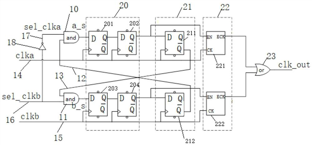
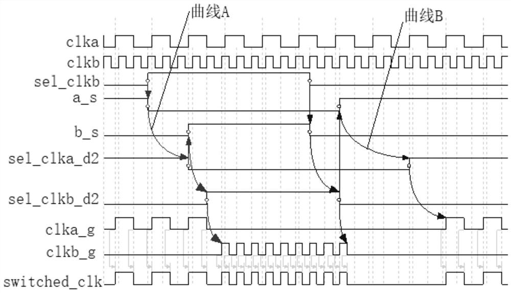
[0031] Please refer to figure 1 , This embodiment provides a clock dynamic switching circuit, which includes: a first AND gate 10, a second AND gate 11, a first clock signal line 14, a second clock signal line 15, a first clock enable signal line 17, The second clock enable signal line 16 , the first feedback signal line 13 , the second feedback signal line 12 , the level synchronization circuit 20 , the clock gating circuit 21 and the OR gate circuit 23 . Wherein, the level synchronization circuit 20 includes a first level synchronization unit and a second level synchronization unit, such as figure 1 The upper half of the mid-level synchronization circuit 20 is a first level synchronization unit, and the lower half is a second level synchronization unit; the output end of the second feedback signal line 12 and the first clock enable signal line 17 are respectively connected to the first level synchronization unit. An input terminal of an AND gate 10 is connected, the output ...


PUM


Abstract

The invention relates to the technical field of circuit design, in particular to a clock dynamic switching circuit. The circuit comprises a first AND gate, a second AND gate, a first clock enable signal line, a second clock enable signal line, a first feedback signal line, a second feedback signal line, a first clock signal line, a second clock signal line, a level synchronization circuit, a clockgating circuit and an OR gate circuit. The level synchronization circuit is used for synchronizing the first clock enable signal line and a first clock signal and synchronizing the second clock enable signal line and a second clock signal, and the clock gating circuit is used for controlling on-off of the clock signals. According to the circuit, the positive edge of the clock is used for triggering all devices in the circuit, a half-cycle path does not exist any more, the highest operation frequency of the circuit is improved, clock glitch is avoided through a feedback mechanism, and signalsoutput by the circuit are free of burrs.

Description

technical field [0001] The invention relates to the technical field of circuit design, in particular to a clock dynamic switching circuit. Background technique [0002] There are usually multiple clocks with different frequencies in the chip, and when they are applied in different power consumption modes, the clocks will be dynamically switched according to the needs. For example, when the chip is running at low power consumption, the clock is switched to a low-frequency clock; when the chip is running at full power, the clock is switched to a high-frequency clock. The frequencies of the high-frequency and low-frequency clocks may not be related, or they may be multiples. The problem that needs to be paid attention to during dynamic clock switching is that clock glitch (glitch) (see Note 1) should be avoided during dynamic clock switching. If an unexpected clock glitch occurs, it may cause fatal abnormal errors on the chip (see Note 1). 2), which is absolutely not allowed ...

Claims


Application Information

Patent Timeline
Patent Type & Authority Applications(China)
IPC IPC(8): G06F1/12H03K5/1252
CPCG06F1/12H03K5/1252
Inventor 郭敬侯晓峰彭永林马彪
Owner 深圳市鹏芯数据技术有限公司
Learn More