
Positionable automatic welding device for machining cooling fin of computer CPU

An automatic welding and heat sink technology, applied in auxiliary devices, welding equipment, auxiliary welding equipment, etc., can solve the problem of low processing efficiency, lack of multiple stations, inconvenient integration of heat sink bearing components and positioning components, etc. problem, achieve the effect of improving cooling efficiency and avoiding offset

Inactive Publication Date: 2020-12-29
东莞市夯牛机电科技有限公司
View PDF0 Cites 1 Cited by
  • Summary
  • Abstract
  • Description
  • Claims
  • Application Information

AI Technical Summary

Problems solved by technology

[0004] The purpose of the present invention is to provide a positionable automatic welding device for heat sink processing of a computer CPU, to solve the problem that the existing computer CPU heat sink processing welding device proposed in the above-mentioned background technology is inconvenient to install the heat sink carrying assembly It is integrated with the positioning component, does not have multiple stations, and the processing efficiency is low. After the welding process is completed, it does not have the function of automatic feeding, and the degree of automation is insufficient.

Method used


Image

  • Positionable automatic welding device for machining cooling fin of computer CPU
  • Positionable automatic welding device for machining cooling fin of computer CPU
  • Positionable automatic welding device for machining cooling fin of computer CPU

Examples


Embodiment Construction

[0026] The technical solutions in the embodiments of the present invention will be clearly and completely described below in conjunction with the accompanying drawings in the embodiments of the present invention. Obviously, the described embodiments are only some of the embodiments of the present invention, not all of them. Based on The embodiments of the present invention and all other embodiments obtained by persons of ordinary skill in the art without making creative efforts belong to the protection scope of the present invention.

[0027] In the description of the present invention, unless otherwise stated, the meaning of "plurality" is two or more; the terms "upper", "lower", "left", "right", "inner", "outer" , "front end", "rear end", "head", "tail", etc. indicate the orientation or positional relationship based on the orientation or positional relationship shown in the drawings, and are only for the convenience of describing the present invention and simplifying the desc...


PUM


Abstract

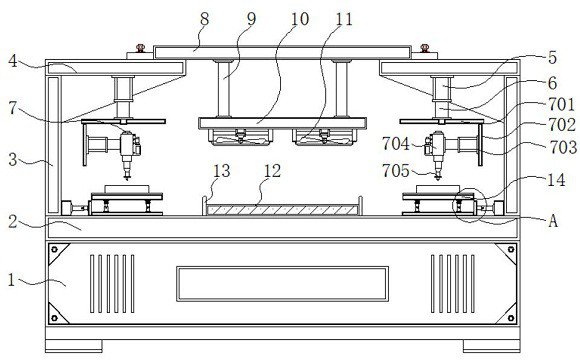
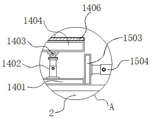
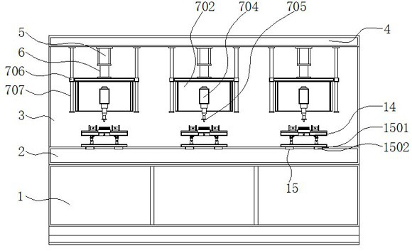
The invention discloses a positionable automatic welding device for machining a cooling fin of a computer CPU and relates to the technical field of cooling fin welding, the positionable automatic welding device comprises a machine body, a welding structure, a conveying belt and a positioning mechanism, a workbench is fixed above the machine body, back plates are installed on the two sides of the outer portion of the upper portion of the workbench, and a top plate is fixed to the upper sides of the back plates. An air cylinder is mounted below the middle of the top plate, a piston rod is arranged on the lower side of the air cylinder, the welding structure is mounted below the piston rod, an upper plate is mounted above the top plate, connecting rods are fixed to the two sides of the lowerportion of the upper plate, a mounting plate is fixed to the lower portions of the connecting rods, and cooling fans are mounted on the two sides of the lower portion of the mounting plate. The positionable automatic welding device has the beneficial effects that the height of a lifting plate can be conveniently adjusted in a rising and falling mode through the air cylinder and the piston rod so as to drive a welding gun and a welding head to descend, the position of the welding gun can be conveniently adjusted through an electric push rod, and a cooling fin main body can be conveniently welded through the welding gun and the welding head.

Description

technical field [0001] The invention relates to the technical field of heat sink welding, in particular to a positionable automatic welding device for processing heat sinks of computer CPUs. Background technique [0002] The heat sink is a device for cooling the heat-prone electronic components in electrical appliances. It is mostly made of aluminum alloy, brass or bronze into plates, sheets, and multi-sheets. For example, the CPU central processing unit in a computer needs to use a large The heat sink of the computer CPU needs to be welded during the processing of the heat sink of the computer CPU, so a welding device is used. Welding, also known as welding and melting, is a method of joining metal or metal by heating, high temperature or high pressure. Manufacturing process and technology of other thermoplastic materials such as plastics. [0003] The existing welding device for heat sink processing of computer CPU is inconvenient to integrate the bearing assembly and pos...

Claims


Application Information

Patent Timeline
IPC IPC(8): B23K37/00B23K37/02B23K37/04
CPCB23K37/00B23K37/003B23K37/0247B23K37/0252B23K37/0443
Inventor 张绍辉杨志翔郭钰儿
Owner 东莞市夯牛机电科技有限公司
Learn More