
High-precision compact integrated joint structure

A joint structure, compact technology, applied in the directions of manipulators, manufacturing tools, joints, etc., can solve the dual requirements of joint lightness and high precision, the external encoder cannot detect the backlash of the reducer transmission process, and the reducer is anti-overturning. The torque has not been enhanced and other problems, to achieve the effect of enhancing the space radiation protection capability, improving the anti-overturning moment and joint output accuracy, and improving the repeatability

Pending Publication Date: 2020-12-29
南京安舍曼机器人研究院有限公司
View PDF0 Cites 3 Cited by
  • Summary
  • Abstract
  • Description
  • Claims
  • Application Information

AI Technical Summary

Problems solved by technology

[0005] The current joints are mainly limited by the following three reasons, resulting in the inability to meet the dual requirements of joints in precision technology fields such as aerospace and aerospace: First, the current design of the joint structure makes the external encoder installed on the motor side. Hall (sensor) or relative encoders for motor commutation or vector control
This structure makes the external encoder unable to detect the backlash of the reducer transmission process, and its absolute positioning accuracy decreases when the robot increases the load
[0006] Second, due to the short span of the precision bearings of the RV reducer or harmonic reducer, the joint rotational moment is usually twice the radial anti-overturning moment. The moment is similar, and the anti-overturning moment of the reducer has not been enhanced
Due to nonlinear factors such as gear meshing error and backlash inside the reducer, the current joint module cannot fully reflect its dynamic characteristics and cannot be used in complex working environments

Method used


Image

  • High-precision compact integrated joint structure
  • High-precision compact integrated joint structure

Examples


Embodiment Construction

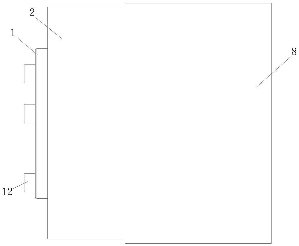
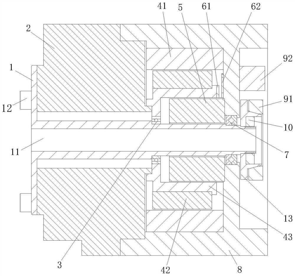
[0026] In this example, refer to figure 1 and figure 2 , the high-precision compact integrated joint structure includes a rotating shaft, a reducer 2, a motor, an integrated brake 5, a relative encoder, an absolute encoder and a joint housing 8, and the input end of the motor and the reducer 2 is assembled and fixed , the rotating shaft is assembled and fixed with the output end of the reducer 2, the joint shell 8 is connected with the reducer 2, and the motor, the integrated brake 5 and the relative encoder are covered inside; the rotating shaft is a hollow feed shaft 1, and its interior has a The middle hole 11 of the cable, the hollow feed shaft 1 runs through the reducer 2 and the joint housing 8, the deep groove ball bearing 3 is arranged between the motor and the hollow feed shaft 1, and the cross roller is arranged between the joint housing 8 and the hollow feed shaft 1 The sub-bearing 7; the absolute encoder is installed on the end of the hollow feed shaft 1 protrudi...


PUM

PropertyMeasurementUnit
Hole diameteraaaaaaaaaa

Abstract

The invention discloses a high-precision compact integrated joint structure. The high-precision compact integrated joint structure comprises a rotating shaft, a speed reducer, a motor, an integrated band-type brake, a relative encoder, an absolute encoder and a joint outer shell, wherein the rotating shaft is a hollow feed shaft, a bearing is arranged between the motor and the hollow feed shaft, and a precision bearing is arranged between the joint outer shell and the hollow feed shaft; the absolute encoder is mounted at one end, extending out of the joint outer shell, of the hollow feed shaft; and the relative encoder and the integrated band-type brake are both mounted in the motor, and the integrated band-type brake is coaxial with the motor. According to the high-precision compact integrated joint structure, the band-type brake, the internal and external encoder reading heads and a motor stator are directly mounted on the joint outer shell at the same time, the band-type brake is placed inside the motor, extra space does not need to be occupied, and the axial length of a joint is reduced; and the feed shaft is connected with the crossed roller bearing, a relative encoder coded disc and a motor input shaft are integrated, the number of parts is reduced, the weight of the joint is reduced, the compactness is improved, and the anti-overturning moment of the joint and the jointoutput precision are improved.

Description

technical field [0001] The invention relates to the technical field of mechanical structure and electrical control, in particular to a control structure mainly applied to robot joints. Background technique [0002] As the core component of the robot, the joint is regarded as the entity of the kinematic pair. It determines the kinematics and kinematic behavior capabilities of the robot, and is the key to ensuring the safe and smooth operation of the robot. The main tasks of joints include generating and transmitting power, position sensing, and mechanical connection. It is mainly composed of motor, reducer, motion shaft system, sensor and harness management device, drive and data acquisition and processing circuit, etc. [0003] The joints of traditional industrial robots usually use "external" servo motors, and the joints contain reducers and brake mechanisms. This structure makes traditional robots have disadvantages such as bulky, dangerous, and difficult to operate. T...

Claims


Application Information

Patent Timeline
IPC IPC(8): B25J17/02
CPCB25J17/02
Inventor 居鹤华
Owner 南京安舍曼机器人研究院有限公司
Learn More