
Injection molding system

An injection molding system and mold technology, applied in the field of injection molding system, can solve the problems of low cost, short production cycle and high cost, and achieve the effect of long production cycle, short production cycle and stable properties.

Pending Publication Date: 2020-12-29
上海梓域材料科技有限公司
View PDF0 Cites 0 Cited by
  • Summary
  • Abstract
  • Description
  • Claims
  • Application Information

AI Technical Summary

Problems solved by technology

[0005] In order to overcome the problems existing in related technologies at least to a certain extent, the purpose of this application is to provide an injection molding system, which utilizes an injection mold to perform injection molding on photosensitive materials. The process is simple, the production cycle is short, and the cost is low. The production cycle of injection molded parts is long, the process is cumbersome, low efficiency and high cost

Method used


Image

  • Injection molding system
  • Injection molding system

Examples


Embodiment Construction

[0024] Reference will now be made in detail to the exemplary embodiments, examples of which are illustrated in the accompanying drawings. When the following description refers to the accompanying drawings, the same numerals in different drawings refer to the same or similar elements unless otherwise indicated. The implementations described in the following exemplary embodiments do not represent all implementations consistent with this application. Rather, they are merely examples of means consistent with aspects of the present application as recited in the appended claims.

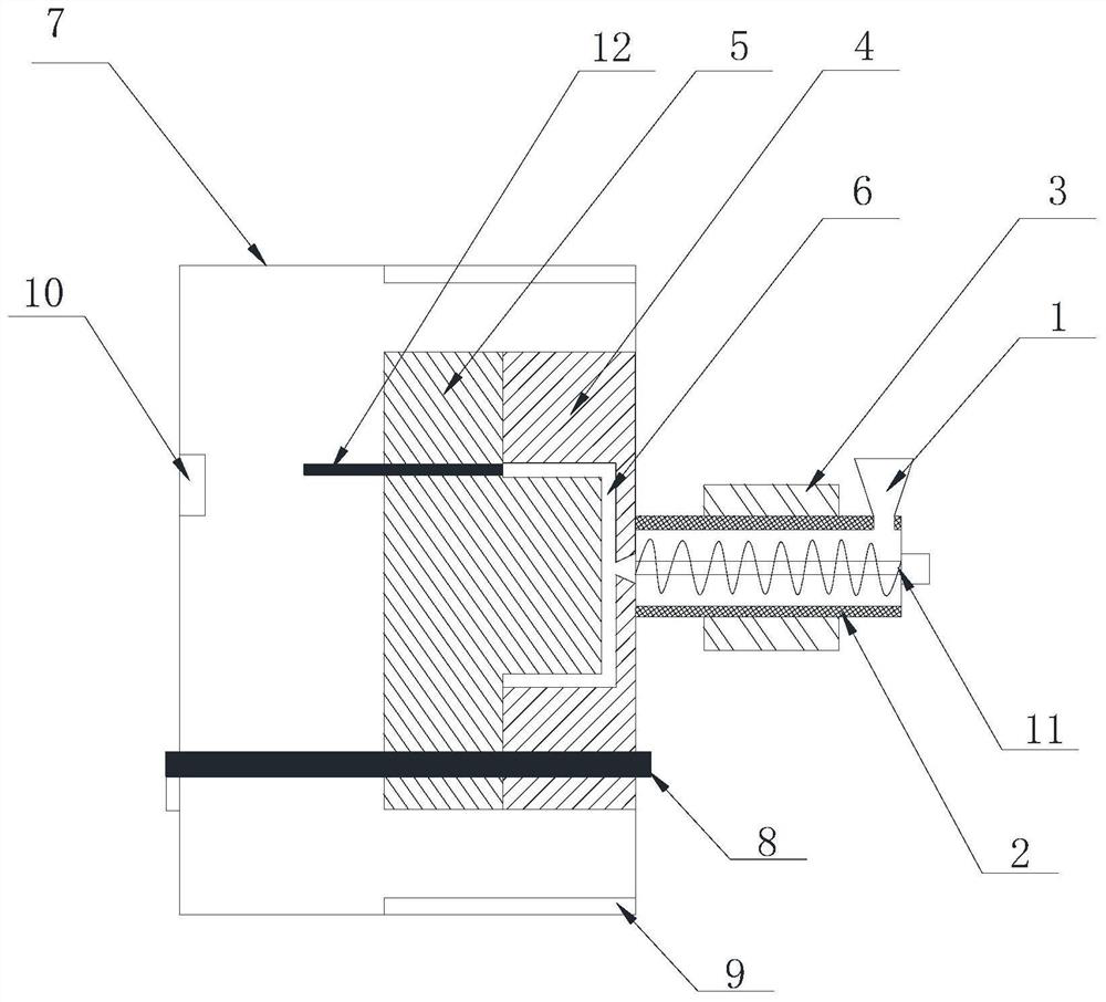
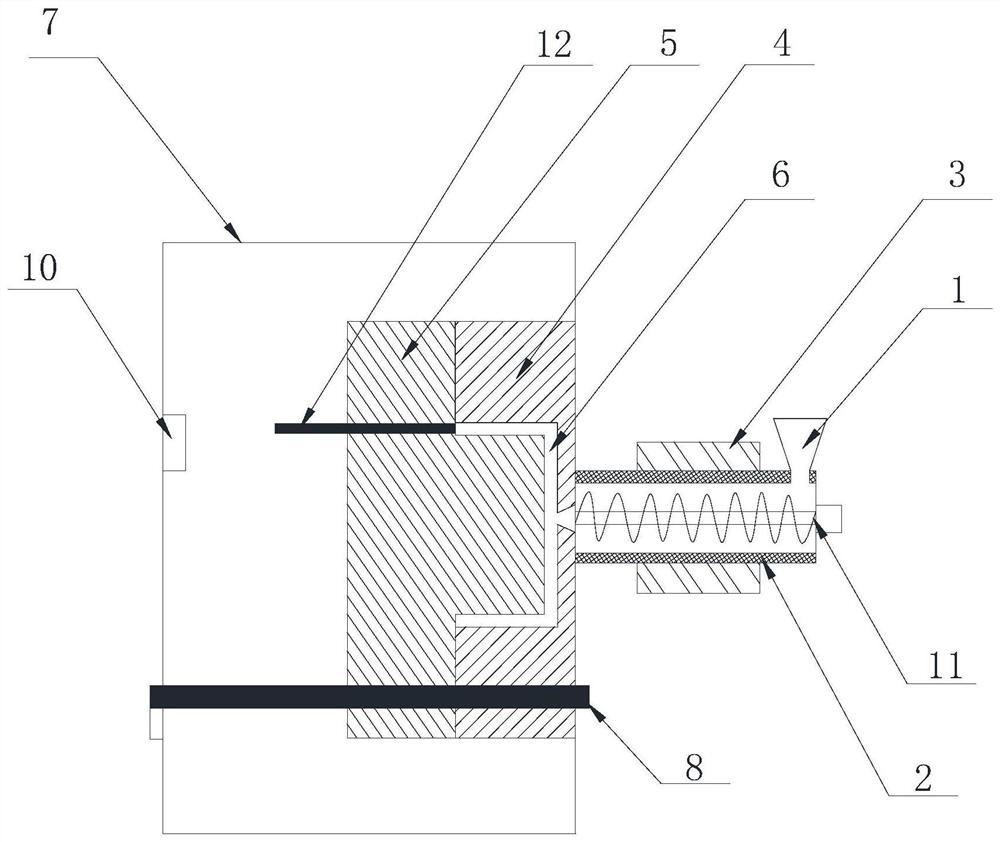
[0025] refer to Figure 1-Figure 2 , the specific embodiment provides an injection molding system, including a plastic mold for making a model and a feeding device for feeding liquid photosensitive materials into the plastic mold, and the plastic mold is provided with a cavity 6 for The liquid photosensitive material forms a model in the cavity 6 , and the feeding device communicates with the cavity 6 fo...


PUM


Abstract

The invention discloses an injection molding system which comprises a shaping mold for manufacturing a model, a feeding device for allowing a liquid photosensitive material to enter the shaping mold,and an ultraviolet irradiation device for curing the model, and the shaping mold is provided with a cavity for allowing the liquid photosensitive material to form the model. The cavity communicates with the feeding device, and the shaping mold is made of a transparent material. By means of the arrangement, the problems that an existing injection molding part is long in manufacturing period, complex in procedure, low in efficiency and high in cost are solved.

Description

technical field [0001] The present application relates to the technical field of injection molding, and more specifically, relates to an injection molding system. Background technique [0002] With the increasing demands of modern design and products, injection molding has become one of the most popular ways to realize the appearance of products. The advantages of injection molding are that the cost per piece is extremely low in mass production, and generally various plastics have high stability and good resistance. , with a wide range of options to create a more designer look. [0003] The main implementation method is to heat the selected plastic particles to make them into a molten state, and then extrude the molten plastic particles into the pre-made steel mold by extrusion, and enter the steel mold Finally, as the plastic particles in the molten state are separated from the heat source, the temperature decreases and they no longer have fluidity. After cooling down comp...

Claims


Application Information

Patent Timeline
Patent Type & Authority Applications(China)
IPC IPC(8): B29C35/08B29C45/26B29C45/40B29C45/47B29C45/66B29C45/73B29C45/74
CPCB29C35/0805B29C45/2602B29C45/4005B29C45/47B29C45/66B29C45/73B29C45/74B29C2035/0827
Inventor 杨清
Owner 上海梓域材料科技有限公司
Learn More