
Gas supply device

A technology of air supply device and air supply valve, applied in ion implantation plating, metal material coating process, coating and other directions, can solve the problems of difficult to control the flow rate of selenium gas, low yield and uneven distribution, etc.

Inactive Publication Date: 2020-12-29
山西米亚索乐装备科技有限公司
View PDF0 Cites 0 Cited by
  • Summary
  • Abstract
  • Description
  • Claims
  • Application Information

AI Technical Summary

Problems solved by technology

However, selenium is a metalloid element, and its characteristics in the gaseous state are somewhat different from those of metal elements after gasification. Directly applying the gas supply form of metal vapor makes it difficult to control the flow rate of selenium gas in the nozzle, and the selenium gas enters the coating from the nozzle The diffusion process after the cavity is not easy to control
In the case of control errors in both the selenium gas flow rate and the diffusion process, the selenium gas is prone to uneven distribution in the coating chamber, resulting in uneven selenization reaction of target sputtering
In the CIGS sputtering production process, when a certain amount of selenium gas is introduced, the power generation efficiency of the same batch of CIGS power generation chips varies greatly, the yield rate is low, the cost of production and screening is high, and it is not conducive to quality control

Method used

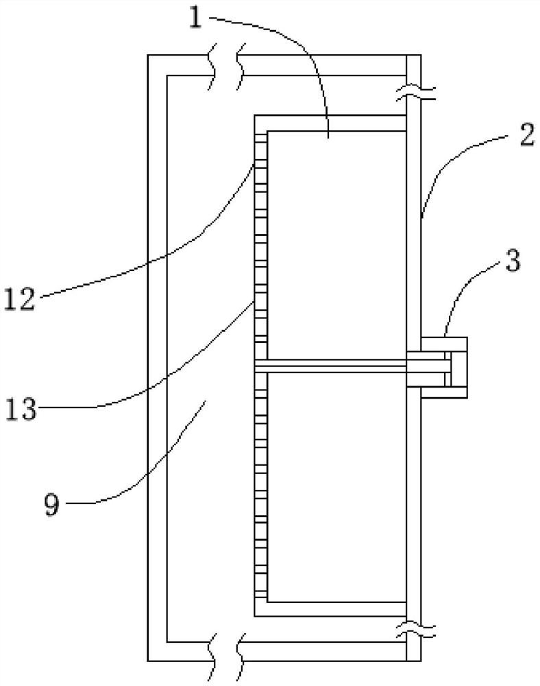
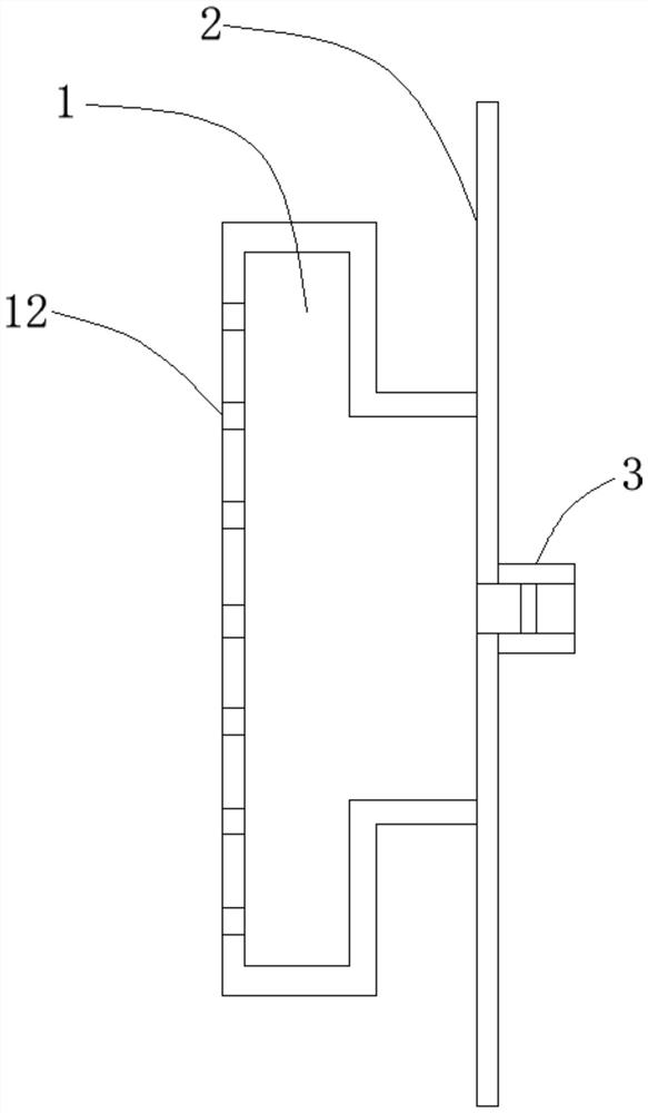
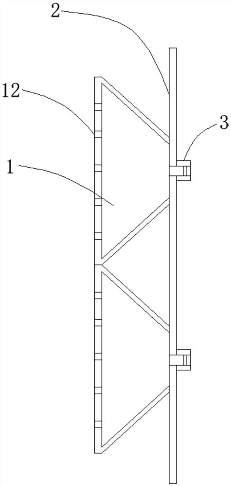

Image

  • Gas supply device
  • Gas supply device
  • Gas supply device

Examples


Embodiment Construction

[0017] The technical solutions in the embodiments of the present application will be clearly and completely described below in conjunction with the accompanying drawings in the embodiments of the present application. Obviously, the described embodiments are part of the embodiments of the present application, not all of them. Based on the embodiments in this application, all other embodiments obtained by persons of ordinary skill in the art without making creative efforts belong to the scope of protection of this application. "First", "second" and similar words used in this application do not indicate any order, quantity or importance, but are only used to distinguish different components. In the description of the present application, it is to be understood that the terms "upper", "lower", "front", "rear", "left", "right", "vertical", "horizontal", "top", The orientation or positional relationship indicated by "bottom", "inner", "outer", "clockwise", "counterclockwise", etc. i...


PUM


Abstract

The invention provides a gas supply device. The gas supply device comprises at least one gas homogenizing chamber and a mounting plate; the gas homogenizing chambers are used for buffering atmospheregas and then outputting the atmosphere gas to a coating cavity; each of the gas homogenizing chambers is provided with at least one gas inlet and a plurality of gas outlet holes used for conveying theatmosphere gas to the coating cavity; and the mounting plate is used for sealing and fixing the gas homogenizing chambers and the coating cavity together. According to the gas supply device, atmospheric gas flow is buffered evenly through the gas homogenizing chambers and then conveyed into the coating cavity through the gas outlet holes, so that the pressure of the buffered atmospheric gas is uniform, and the flowing-out speed of the buffered atmospheric gas from the gas outlet holes tends to be uniform.

Description

technical field [0001] The present application relates to the field of sputter coating technology equipment, in particular to a gas supply device. Background technique [0002] Sputtering coating can be simply understood as the use of electrons or high-energy lasers to bombard the target, so that the target surface components are sputtered out in the form of atomic groups or ions, and finally deposited on the surface of the substrate to form a thin film. During the sputtering coating process, it is necessary to evacuate the coating chamber to a specific atmosphere gas according to the coating material, and perform coating in a specific gas atmosphere. [0003] In the production process of thin-film solar cells, copper indium gallium needs to be sputtered onto the substrate in a selenium atmosphere to form a CIGS functional film layer. At present, the gas supply device adopted by the selenium gas atmosphere is the mode of the selenium gas pipeline and the valve, and the sele...

Claims


Application Information

Patent Timeline
IPC IPC(8): C23C14/34C23C14/06
CPCC23C14/06C23C14/34
Inventor 张伟江振南杨永雷见东伟邬英
Owner 山西米亚索乐装备科技有限公司
Learn More