Machining equipment and method for molded pulp product

A technology of pulp molding and machining, which is applied in textiles and papermaking, can solve the problems of high cost, affecting feeding and retrieving, and inconvenient feeding and unloading, etc., and achieves the effect of low manufacturing cost

Active Publication Date: 2020-12-29
ZHEJIANG SHURCON MFG
View PDF9 Cites 4 Cited by
  • Summary
  • Abstract
  • Description
  • Claims
  • Application Information

AI Technical Summary

Problems solved by technology

The disadvantage of this method is that the mold wheel walks around a circle, and its efficiency is low. At the same time, it is necessary to design a circle of mold wheel walking guide track, which temporarily uses a large volume and high cost, and is not easy to pick and place materials.
[0008] In addition, the Chinese patent also discloses a servo forming device for controllable feed processing of the ring buckle of the pulp cup lid, CN201922057581.3. In this scheme, mechanical equipment is used to extrude the pulp cup lid in the later stage, and the lower mold is located at the...

Method used


Image

  • Machining equipment and method for molded pulp product
  • Machining equipment and method for molded pulp product
  • Machining equipment and method for molded pulp product

Examples


Embodiment 1

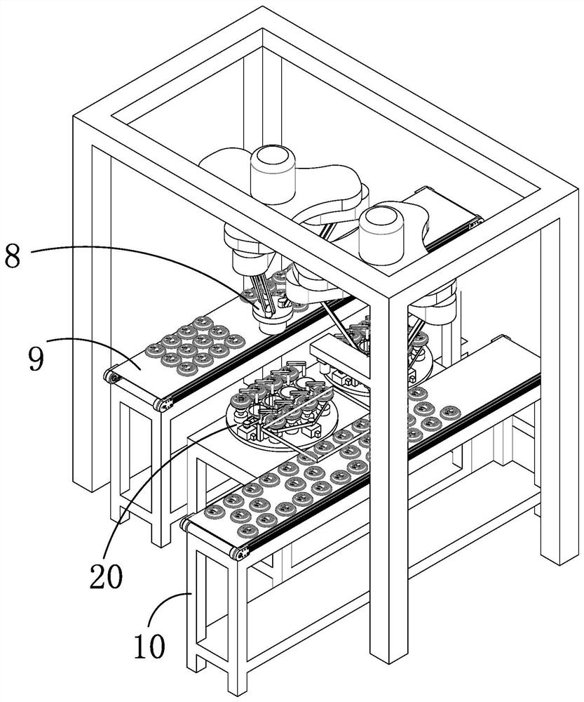
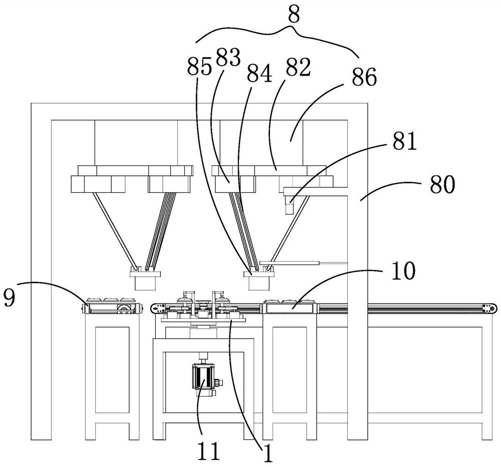
[0045] like figure 1 and figure 2 As shown, taking the processing of rolled pulp molded products as an example, a machining equipment for pulp molded products includes a feeding unit 10 for feeding and conveying unrolled pulp molded products; the feeding unit 10 for the conveyor belt.

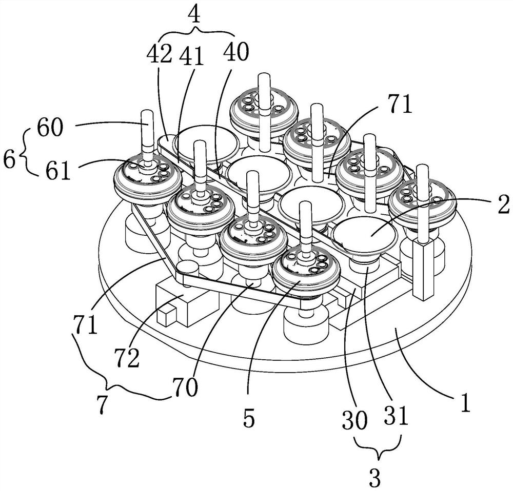
[0046] Rolling units 20 , preferably, there are two rolling units 20 in this embodiment and they are spaced in a straight line. The rolling units 20 are rotatably connected to the frame 21 . Specifically, the rolling unit 20 includes a horizontal turntable 1 rotatably connected to a frame, and a turntable drive motor 11 for driving the horizontal turntable 1 is provided on the frame.

[0047] At least one translation rolling wheel 2 is horizontally slidably connected to the upper surface of the horizontal turntable 1, and the translation rolling wheel 2 is connected to the translation driving mechanism 3 and the translation rolling wheel 2 is connected to the rotation driving mechanism 4. T...

Embodiment 2

[0072] The working principle and structure of this embodiment are basically the same as those of Embodiment 1, and the different structure is that there are 3-6 rolling units 20 .

Embodiment 3

[0074] The working principle and structure of this embodiment are basically the same as those of Embodiment 1. The different structures are: there is one rolling unit 20, and one loading and unloading unit, and the unloading action is performed after unloading.


PUM


Abstract

The invention discloses machining equipment for a molded pulp product. The equipment comprises a feeding unit, a rolling/rotary cutting unit which comprises a horizontal rotary disc, wherein at leastone translation rolling/rotary cutting wheel is horizontally connected to the upper surface of the horizontal rotary disc in a sliding mode, the translation rolling/rotary cutting wheel is connected with a translation driving mechanism, and the translation rolling/rotary cutting wheel is connected with a rotary driving mechanism, the upper surface of the horizontal rotary disc is rotationally connected with two rolling/rotary cutting movable dies which are located on the periphery of each horizontal rolling/rotary cutting wheel and symmetrically distributed with the horizontal rolling/rotary cutting wheel as the center, and each rolling/rotary cutting movable die corresponds to one rotary downward pressing assembly, each rolling/rotary cutting movable die corresponds to one rotary drivingmechanism, and the rotary driving mechanisms drive the rolling/rotary cutting movable dies to rotate, and a material taking and placing unit which is used for placing non-rolled/rotary-cut pulp moldedproducts conveyed by the feeding unit on the rolling/rotary cutting movable dies and taking and transferring the rolled/rotary-cut pulp molded products to the outside of the rolling/rotary cutting unit.

Description

technical field [0001] The invention belongs to the technical field of pulp molded product processing, and in particular relates to a machining equipment and method for pulp molded products. Background technique [0002] Pulp molded products, including pulp molded lids, cups and other container products. [0003] When the lid and the cup are combined, in order to ensure airtightness and anti-off performance, a ring buckle design is generally made on either side. [0004] The current design of this ring buckle is processed in the pulp molding process to achieve the above-mentioned sealing and anti-off properties. Although this method can meet the requirements of use to a certain extent, it has the following defects: [0005] It will lead to a structure of unequal thickness, and the amount of material input will increase; [0006] Secondly, it increases the difficulty and cost of mold opening. [0007] In order to improve the defects of the prior art, for example, Chinese ...

Claims


Application Information

Patent Timeline
IPC IPC(8): D21J5/00
CPCD21J5/00
Inventor 潘耀华胡峻珲王楷胡庆军岑刚
Owner ZHEJIANG SHURCON MFG
Why Eureka
Try Eureka