Condensate water recycling equipment
A technology for condensed water and equipment, which is applied in the field of condensed water recycling equipment, can solve the problems of dirty condensed water, reduced practicability of the overall mechanism, and inconvenient cleaning.
- Summary
- Abstract
- Description
- Claims
- Application Information
AI Technical Summary
Problems solved by technology
Method used
Image

Examples
Embodiment 1
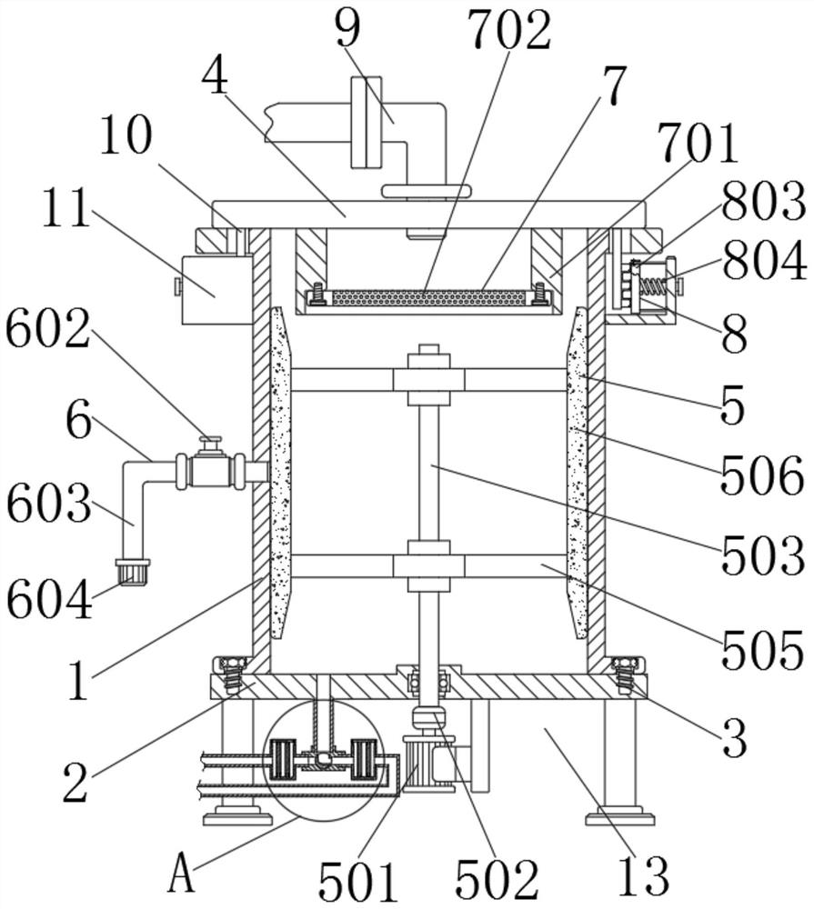
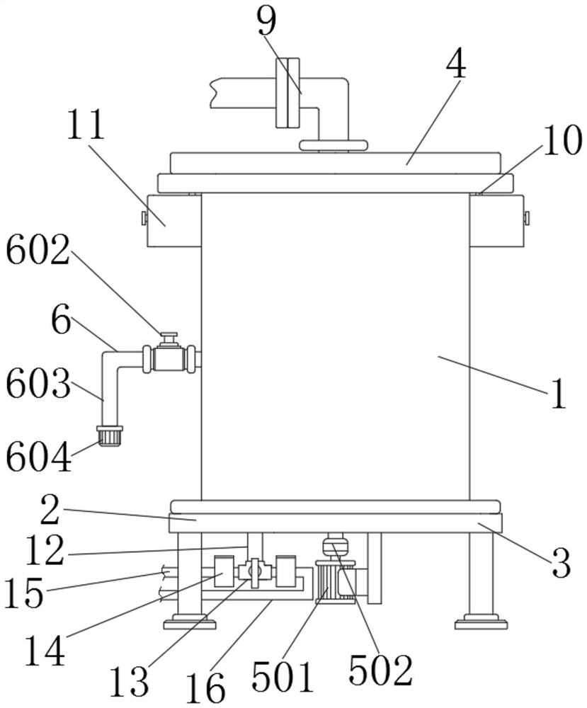
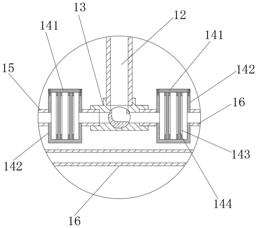
[0040] A condensed water recovery and utilization device, including a shell 1, a support 2, a bolt 3 and a cover plate 4, the bottom of the shell 1 is provided with a support 2, and the outer wall of the support 2 is screwed to the shell 1 through the bolt 3 , the bolt 3 connects the shell 1 and the support 2 together, the top of the shell 1 is installed with a cover plate 4, and the inside of the support 2 is equipped with a power mechanism 5, the power mechanism 5 includes a motor 501, a coupling 502, a vertical Rod 503, bearing 504, horizontal plate 505 and scraper 506, the right end of the motor 501 is fixedly connected to the support 2, the motor 501 is a 220V servo motor, the top of the output shaft of the motor 501 is fixed to the vertical rod 503 through the coupling 502 Then, the outer wall of the vertical bar 503 is movably connected with the support 2 through the bearing 504, the motor 501 drives the vertical bar 503 to rotate through the coupling 502, the outer wall...
Embodiment 2
[0042] As an option, see Figure 1-5 , Condensed water recovery and utilization equipment, the middle position of the upper surface of the cover plate 4 is connected with a water inlet pipe 9, and the water inlet pipe 9 guides the condensed water into the housing 1, and the left and right sides of the lower surface of the cover plate 4 are fixedly connected with inserting plates 10 , the inside of the board 10 is processed with grooves, the outer walls of the two boards 10 are in clearance fit with the housing 1, the board 10 penetrates the edge of the housing 1 and enters the housing 11, and the tops of the left and right sides of the housing 1 are The outer shell 11 is fixedly connected, and the inside of the support 2 is sleeved with a water outlet pipe 12. The outer walls of the two water outlet pipes 12 are interference fit with the support 2. The water outlet pipe 12 leads out the condensed water in the shell 1. The interior of the housing is communicated with the housin...
Embodiment 3
[0046] As an option, see figure 1 , 2 and 7, condensed water recycling equipment, a sampling mechanism 6 is installed in the middle of the left side of the housing 1, and the sampling mechanism 6 includes a connecting pipe 601, a control valve 602, a curved pipe 603 and a threaded cap 604, and the right end of the connecting pipe 601 is connected to the shell Body 1 is connected to each other, and a control valve 602 is installed inside the connecting pipe 601. The connecting pipe 601 leads out the condensed water in the shell 1. The left end of the connecting pipe 601 is connected with a curved pipe 603. Cap 604, open the threaded cap 604 to lead out the water in the curved pipe 603 to complete the sampling, and the connecting pipe 601 is vertically arranged with the casing 1 .
[0047] The solution in this embodiment can be selectively used in combination with the solutions in other embodiments.
PUM
 Abstract
Description
Claims
Application Information
 - R&D
- Intellectual Property
- Life Sciences
- Materials
- Tech Scout
- Unparalleled Data Quality
- Higher Quality Content
- 60% Fewer Hallucinations
Browse by: Latest US Patents, China's latest patents, Technical Efficacy Thesaurus, Application Domain, Technology Topic, Popular Technical Reports.
© 2025 PatSnap. All rights reserved.Legal|Privacy policy|Modern Slavery Act Transparency Statement|Sitemap|About US| Contact US: help@patsnap.com