
High-stability heat dissipation battery pack structure

A high-stability battery pack technology, applied in secondary batteries, structural parts, battery pack components, etc., can solve the problems of low heat dissipation efficiency, poor temperature consistency, and low safety of battery cells

Inactive Publication Date: 2020-12-29
陈鸿文
View PDF21 Cites 0 Cited by
  • Summary
  • Abstract
  • Description
  • Claims
  • Application Information

AI Technical Summary

Problems solved by technology

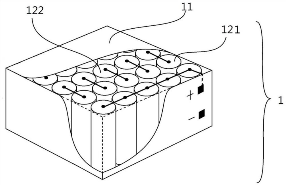
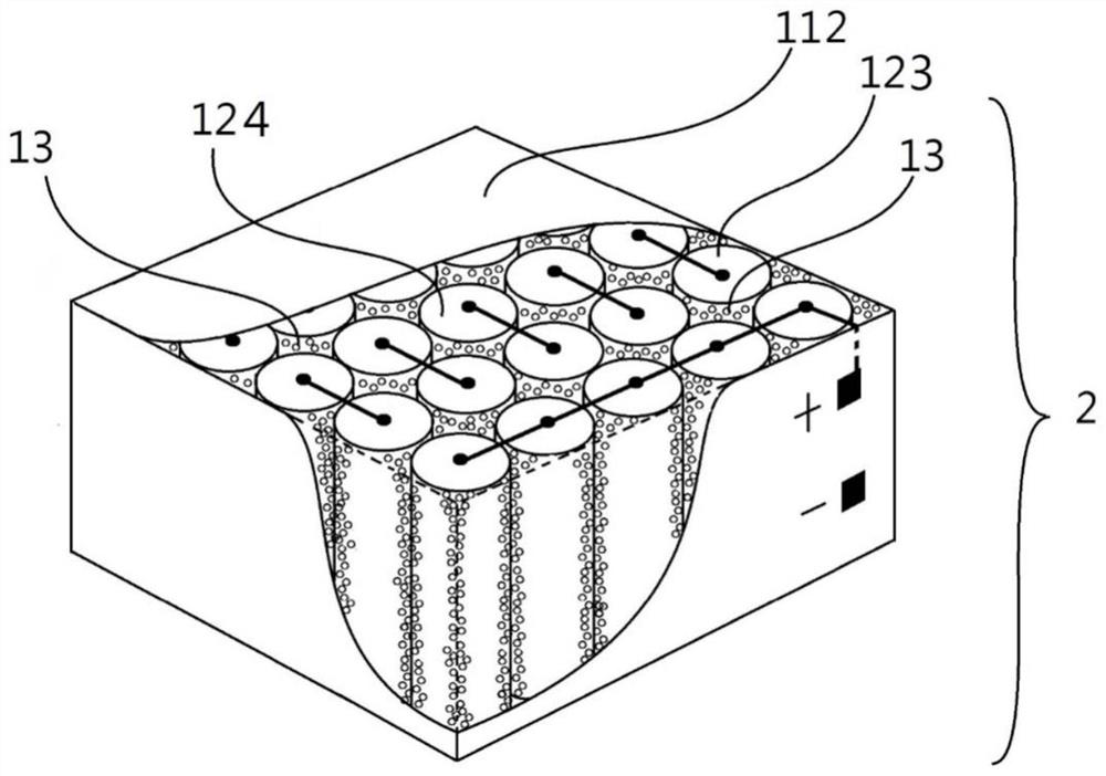
[0008] The purpose of the battery pack structure with high stability and heat dissipation of the present invention is to provide a high heat dissipation device for the existing power battery pack device, which has the defects of low heat dissipation efficiency, poor temperature consistency, and low safety of the battery cells in the plastic outer shell. The outer casing, in order to reduce the temperature difference between the battery cells, has a high heat conduction path, high safety material and structure technology, can realize the inventive device of the high heat dissipation outer casing battery pack

Method used


Image

  • High-stability heat dissipation battery pack structure
  • High-stability heat dissipation battery pack structure

Examples


Embodiment 1

[0040] Composite phase change materials are used to meet the needs of batteries, and the temperature of the phase change point is 65°C, and the insulation resistance is >10 10 Ω, thermal conductivity of 1.0 (W / K·M), latent heat value of 130 (J / g).

[0041] In this composite phase change material, the content is 86wt% stearic acid, 2wt% graphite powder, 0.6wt% carbon nanosphere particles, 0.4wt% graphene, 6wt% aluminum hydroxide powder , 5wt% content of calcium magnesium carbonate powder.

[0042] The battery pack uses a high heat dissipation shell, the shell material, the content of polycarbonate 88wt%, the content of 1wt% carbon spheres, 0.5wt% graphene, 1.5wt% graphite, 5wt% alumina, 4wt% calcium magnesium silicon Salt composition, the outer casing adopts insulation resistance>10 10 Ω, thermal conductivity of 0.9 (W / K · M) characteristics of materials.

[0043] The implementation method of the battery structure with high stability and heat dissipation composite function o...

Embodiment 2

[0045] Composite phase change materials are used to meet the needs of batteries, and the temperature of the phase change point is 75°C, and the insulation resistance is >10 10 Ω, thermal conductivity 0.8(W / K·M), latent heat value up to 110(J / g).

[0046] In this composite phase change material, the content is 47wt% stearic acid, 37wt% paraffin, 3wt% graphite powder, 1.5wt% carbon nanosphere particles, 0.5wt% graphene, 2wt% hollow glass spheres , 4wt% content of inorganic phosphorus compound powder, 5wt% content of nano layered silicate powder.

[0047] The battery pack uses a high heat dissipation shell, the shell material, the content of polycarbonate 85wt%, the content of 1wt% carbon spheres, 0.5wt% graphene, 2.5wt% graphite, 6wt% alumina, 5wt% calcium magnesium silicon Salt composition, the outer casing adopts insulation resistance>10 10 Ω, thermal conductivity of 1.0 (W / K·M) characteristic materials.

[0048] For the battery with high stability and heat dissipation, a g...


PUM

PropertyMeasurementUnit
Phase transition temperatureaaaaaaaaaa
Insulation resistanceaaaaaaaaaa
Latent heataaaaaaaaaa

Abstract

The invention provides a high-stability heat-dissipation battery pack structure which comprises a high-heat-dissipation outer shell and a composite phase change material arranged in a gap between a battery unit and the outer shell. The composite phase change material is hermetically filled in a battery pack of the high-heat-dissipation outer shell, so that a battery has a good heat dissipation mechanism in a normal working state. The high-heat surge generated during high-current charging and discharging is absorbed by the composite phase-change material to buffer temperature rise so as to reduce temperature difference among the battery units, and then the high-heat surge is connected with the high-heat-dissipation outer shell through the high-heat-conduction composite phase-change materialand is discharged out of the battery pack in a heat radiation mode so as to achieve the purpose of heat dissipation.

Description

technical field [0001] The invention belongs to the technical field of power battery temperature control, and in particular relates to a heat dissipation method combining a battery and a composite phase change material. Background technique [0002] The high-power and large-capacity lithium-ion battery pack is an ideal energy storage power source for high-power equipment. Generally, multiple battery cells are connected in series or parallel in different forms to form a battery pack, and then multiple battery packs are connected in series and parallel to form a larger battery pack to provide the required voltage or current. [0003] Generally, the battery pack is composed of multiple battery cells, which are densely connected in series and parallel in a sealed insulating casing. When charging and discharging rapidly, the temperature of the battery cells will rise rapidly, and the temperature has a double impact on the battery: the higher the temperature, the higher the intern...

Claims


Application Information

Patent Timeline
IPC IPC(8): H01M10/613H01M2/10H01M10/0525H01M10/659
CPCH01M10/613H01M10/0525H01M10/659Y02E60/10
Inventor 陈鸿文
Owner 陈鸿文
Learn More